Operation Manual no. BP/IO/21/16 ed. 5.2.1
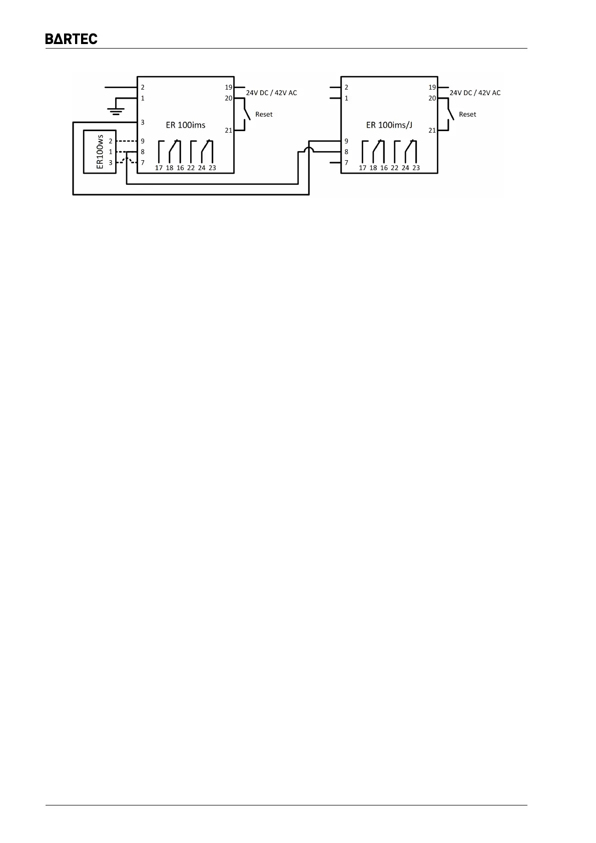
Figure 2: Implementation of the warning signal
is possible to control the executive stage from the other device, which allows for additional warning
signal (Fig. 2). Resetting of the fault state is accomplished by shorting the terminals 20 and 21.
8.2.2 Principle of operation
The ER 100ims works by measuring the resistance between terminals 1 and 2. When the
measured resistance falls below the value set with the potentiometer on the front of the device,
the output relay is deactivated. If the automatic reset function is activated after the resistance has
been increased, the relay is switched on again. When this function is inactive, it must be reset
using the RESET button on the front of the unit or by shorting the terminals 20 and 21. The blue
OK LED indicates the correct insulation status. While, the red ERR LED indicates the latching
information of the leakage fault state.
Between terminals 8 and 9 may be connected to external spark-proof devices (ia) of total
internal resistance ≥ 100 kΩ, i.e.:
– Resistance indicator, e.g. ER 100ws.
– Spark-proof separator for work with other systems.
8.2.3 Additional equipment
For single- or three-phase coupling of the safety device with the insulated controlled network
two or three inviolable ED 100i or ED 100 type coupling chokes are necessary to create artificial
zero point or by directly or with single choke to the neutral point of the transformer. The ED 100i
choke was made by winding a high-inductance coil on one core in a filled plastic encapsulation.
Possible connections are shown in Figure 4 and 5.
The ER 100ims safety device may operate with a spark-proof resistance indicator ER 100ws,
which is optional equipment.
9 Resistance indicator ER 100ws
Resistance indicator ER 100ws is a spark-proof device connected and supplied from the spark-
proof part of ER 100ims relay. It consists of a measuring circuit interpreting the measuring signal
received from ER 100ims and displays the result in the form of insulation resistance on the display
installed. The power supply is drawn from ER 100ims and it is 18V DC ± 5%. The resistance
indicator draws a current below 1,5mA.
Page 12 ER 100ims