Operation Manual no. BP/IO/21/16 ed. 5.2.1
ER 100ws
POLSKA Sp. z o.o.
3
1
~
~
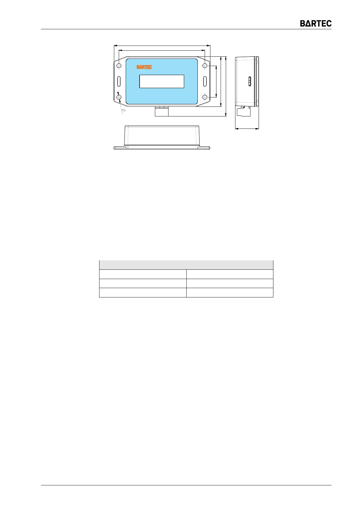
110
98,4
36
57
68,5
5
27,1
Figure 3: Resistance indicator ER 100ws
Resistance indicator ER 100ws is intended for operation in additional enclosure of IP54(65)
protection level.
Resistance indicator ER 100ws is adapted to operation in the following conditions:
• ambient temperature from −20°C to +70°C
• relative humidity up to 95% at 70°C
• working position any
Table 5: Connection of resistance indicator ER 100ws to relay ER 100ims
Terminal ER 100ims Terminal ER 100ws
7 3
8 1
9 2
The indicator has a switch that is suited to subtract from the displayed value typical resistance
for used ED 100i chokes connection. When connecting 2 or 3 chokes, set the switch to „∼3”.
If the connection is applied through one choke, set the switch to „∼1”. Setting the switch in the
middle position disables this function
10 Intrinsically-safe line specifications
10.1 Parameters of ER 100ims
Full device:
U
m
= 250V
For terminals 1 and 2 (measuring input):
U
o
= 18,9V I
o
= 0,42mA P
o
= 2mW L
o
= 1000H
C
o
= 9,07μF L
i
= 404H C
i
≈ 0 (negligible) R
i
= 47kΩ
ER 100ims Page 13