Operation Manual no. BP/IO/21/16 ed. 5.2.1
ER 100ims
2
1
L1
L2
L3
R
R
R
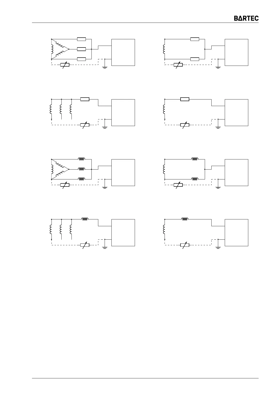
(a) Central protection for 3-phase mains
(preferred connection layout no. 1, ≤ 230V)
ER 100ims
2
1
L
N
R
R
(b) Central protection for 1-phase mains
(preferred connection layout no. 1, ≤ 230V)
ER 100ims
2
1L1 L2
L3
N
R
(option)
(c) Central protection for 3-phase mains
(preferred connection layout no. 2, ≤ 230V)
ER 100ims
2
1
L
N
R
(option)
(d) Central protection for 1-phase mains
(preferred connection layout no. 2, ≤ 230V)
ER 100ims
2
1
L1
L2
L3
ED100i
ED100i
ED100i
(e) Central protection for 3-phase mains
(alternative connection layout no. 1)
ER 100ims
2
1
L
N
ED100i
ED100i
(f) Central protection for 1-phase mains
(alternative connection layout no. 1)
ER 100ims
2
1L1 L2
L3
N
ED100i
(g) Central protection for 3-phase mains
(alternative connection layout no. 2)
ER 100ims
2
1
L
N
ED100i
(h) Central protection for 1-phase mains
(alternative connection layout no. 2)
Figure 4: Wiring connection layout of the earth leakage central trip
(the broken line shows the wiring of a decade resistance box during the configuration of the settings;
for a-d systems, wire resistors of suitable ratings shall be applied)
Indications should be set only after completing settings executed according to the point 11.8.
Settings should be made when voltage of network controlled by relay is switched on.
When relay ER 100ims is already correctly set, then resistance should be connected (e.g. dec-
ade resistor) simulating ground fault with value close to resistance of operation but slightly higher
in a way preventing operation of the relay. Then using potentiometer available near the socket of
ER 100ws display indications of values presented on the LCD display should be corrected to the
value equal to the value of connected simulated resistance of ground fault.
If replacement on one device from previously calibrated pair ER 100ims and ER 100ws is
necessary then displayed value of resistance should be rechecked and corrected if necessary.
ER 100ims Page 17