Operation Manual no. BP/IO/21/16 ed. 5.2.1
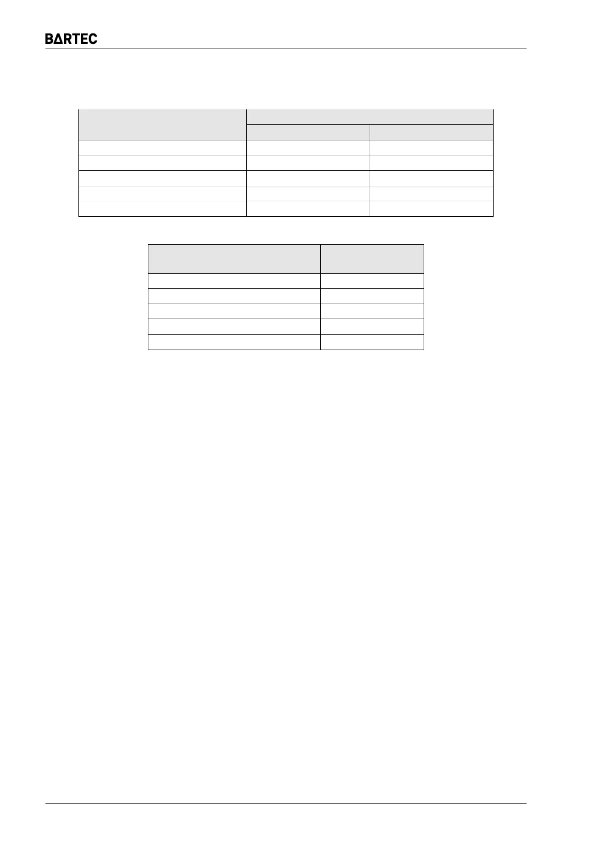
Table 6: PN-G-42040 setting resistance of the earth leakage trip
(a) Central trip
Resistance value [kΩ]
Mains / wiring system rated
voltage (U) [V AC]
Three-phase mains Single-phase mains
U ≤ 127 (133) 4 4
127 (133) < U ≤ 220 (230) 7 7
220 (230) < U ≤ 500 15 15
500 < U ≤ 1000 30 30
1140 60 60
(b) Interlocking trip
Mains / wiring system rated
voltage (U) [V AC]
Resistance value
[kΩ]
U ≤ 42 7
42 < U ≤ 220 (230) 15
220 (230) < U ≤ 500 25
500 < U ≤ 1000 50
1140 100
It is also possibile to set the device by direct connection of the decade resistance to terminals
1 and 2 of the protection:
When configuring the earth leakage central trip settings (Fig. 4)), remember that alternative
(injected) resistance of the wired chokes or resistors. The value of this resistance depends on the
wiring configuration of the monitored mains. The resistance of a single ED 100i choke is 7,1-7,5
kΩ ± 20%. Example: the wiring configuration shown in Fig. 4e features a parallel connection of
three resistors (and where constant component transformer provides the short-circuit); the wiring
configuration shown in Fig. 4g provides a single functional choke (the mains phases are not
interconnected).
For a interlocking trip (see Fig. 5), two scenarios can exist. First, no load is connected, as
shown in Fig. 5a and 5b. In this scenario the mains phases are not interconnected and the
injected resistance is equal to the resistance of a single choke. Second, a load is connected to
the outlet line, as shown in Fig 5c and 5d. Here, the phases are shorted (via a motor for the
constant component) and the injected resistance is equal to the resistance of the chokes wired in
parallel.
To determine the injection resistance for the central and earth leakage trip with loads other
than an electric motors, each case must be considered individually.
WARNING: Only one earth leakage trip can be operated in the given section of the supply
mains. The interlocking trips must be isolated from the monitored mains when the outlet
is online – the interlocking trips must not be online with the supply voltage connected to
the load.
11.9 Setting of indication of ER 100ws display
The indicator is factory calibrated and displays the correct value of the measured resistance.
However, if for some reason it is necessary to correct the indicated value, it can be done with the
potentiometer built into the indicator.
Page 16 ER 100ims