Bartels Mikrotechnik GmbH,
, 44227 Dortmund, Germany
www.micro-components.com, microComponents@bartels-mikrotechnik.de
Tel: +49-231-9742-500, Fax: +49-231-9742-501
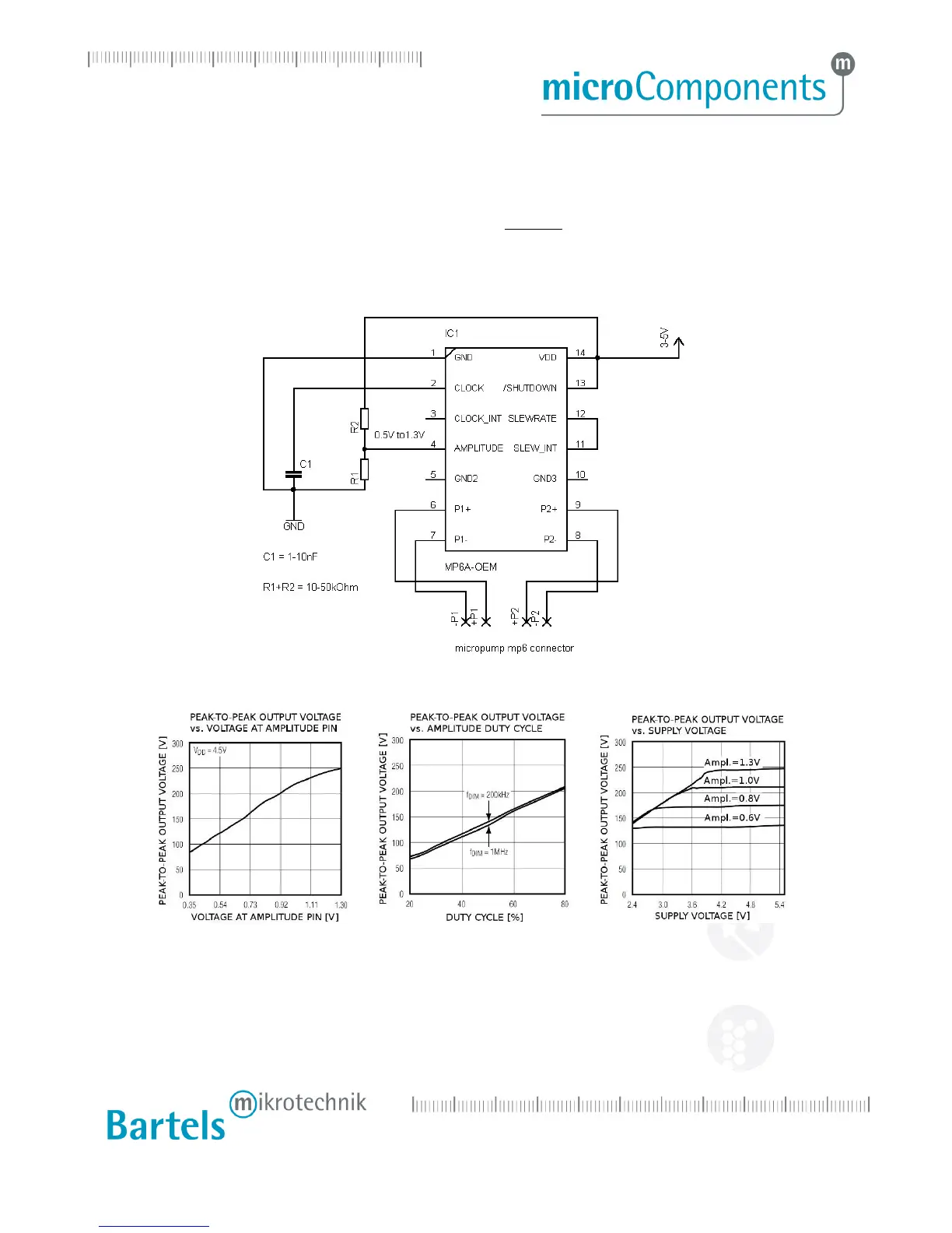
To set the amplitude, either a potentiometer with 10 kOhms, or a voltage divider of two resistors R1 and R2
as shown in the schematic 2 can be used. The voltage at the amplitude pin can be calculated with the
following formula (voltage divider)
R
VV
DDAMPLITUDE
+
⋅=
The relation between the voltage at the amplitude pin and the output voltage is shown in table 7.1
Schematic 2: Frequency and amplitude set with external components
Table 6.1 : Behavior of output voltage according to external circuitry
To set the frequency, a capacitor C1 between in the nF range can be used as shown in the schematic 2
above. Typical capacitor values are shown in the following table 6.1.
For frequencies that are lower than 20 Hz, an external frequency signal needs to be applied as described in
chapter 6.4.3.
 Loading...