www.micro-components.com, microComponents@bartels-mikrotechnik.de
Tel: +49-231-9742-500, Fax: +49-231-9742-501
6.5 Electrical characteristics
One mp6 connected, internally defined frequency and slew rate
(1) Output signal set by internal components
6.6 Pin description
VDD Power supply voltage
GND Ground
SHUTDOWN To shutdown the device, AMPLITUDE and SHUTDOWN needs to be tied to GND.
CLOCK Output frequency control, the frequency can be set to nominal 100 Hz by connecting this
pin to CLOCK_INT (Schematic 1)
A capacitor of 1 to 10 nF can be connected between this pin and GND to set another
frequency (Schematic 2)
The output frequency can be set by a clock signal with four times the desired output
frequency
CLOCK_INT Output frequency control, the frequency can be set to nominal 100 Hz by connecting this
pin to CLOCK
AMPLITUDE Apply a DC Voltage (0-1.3 V) or a PWM signal (0.2-1 MHz) to this input to adjust the
amplitude of the output from 100 V to 235 V
SLEWRATE Slew rate control. This pin is connected to SLEW_INT
SLEW_INT Internal slew rate resistance, connect this pin to SLEW
GND2, GND3 Internally connected to GND, can be left unconnected
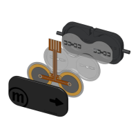
+P1 Piezo 1 positive (see connection diagram for the mp6)
-P1 Piezo 1 negative (see connection diagram for the mp6)
+P2 Piezo 2 positive (see connection diagram for the mp6)
-P2 Piezo 2 negative (see connection diagram for the mp6)
6.7 Noise reduction
If the noise generated by the pump is critical a series resistor of 2-10 kΩ in the P1+ and the P2+ line
between the mp6-OEM and the pump will help. There is no limit for the resistor value but it will decrease
the maximum pump performance.