Page 61 of 82 OM0408/49
Place the equipment on a suitable non-magnetic bench with access to a mains electricity supply
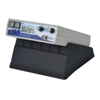
but away from potential sources of electrical noise, e.g. large electric motors. Figure 23 shows
the equipment layed out in close formation, from the left: MS2/3 Meter, MS2WF Furnace, MS2W
sensor, MS2WFP Power Supply. .
Figure 23. X/T Equipment .
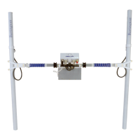
Plug in the mains supply. Connect the silver shielded cable to the MS2WF, the RS232 connections
to the computer and MS2/3, and the power connections to the water pump and flow meter. The
connections on the MS2WFP are shown in Figure 24 below.
Figure 24. MS2WFP Connections