5-6 BE1-32R, BE1-32O/U Testing 9171100990 Rev R
NOTES
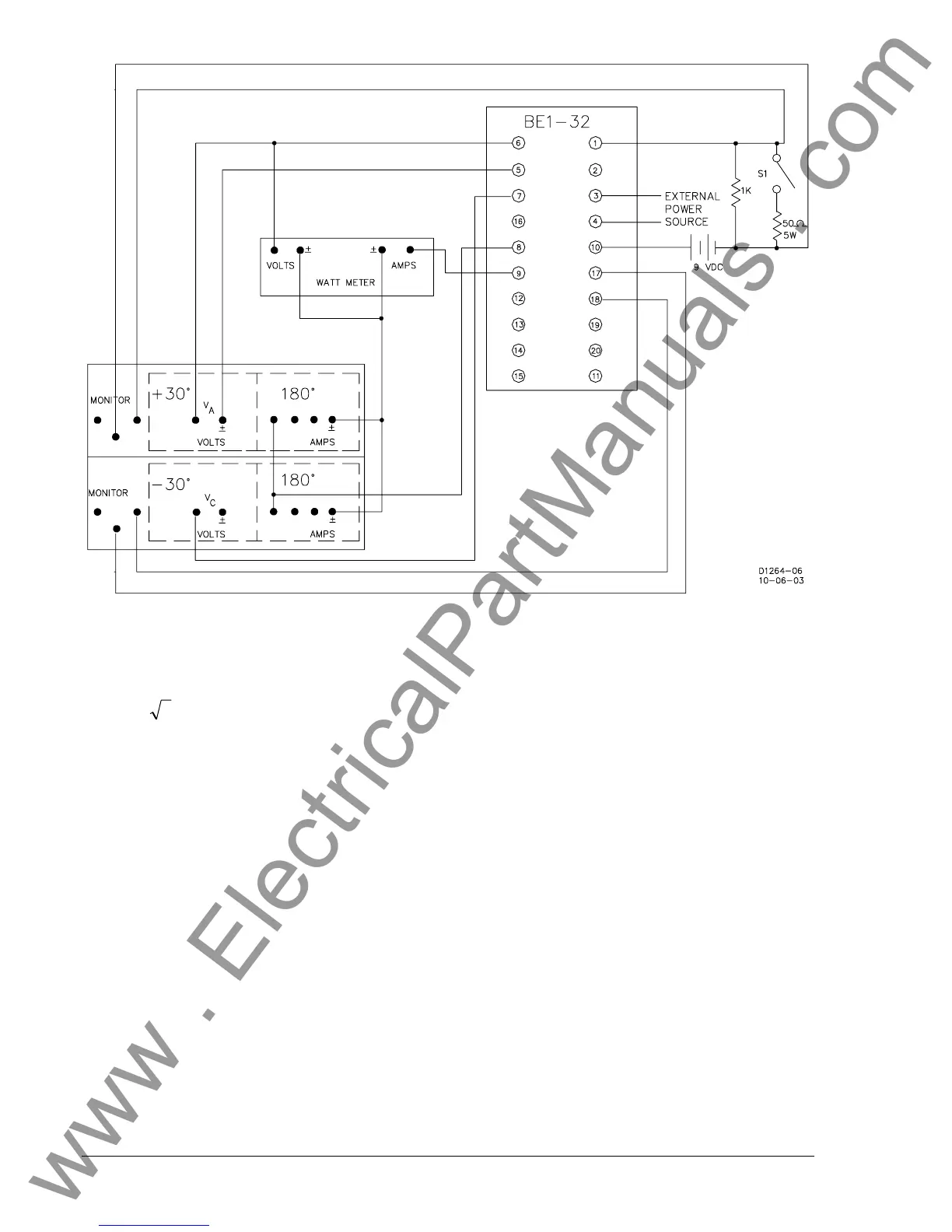
1. Type C (Scott or T-connected) sensing is calibrated in three-phase watts. If a wattmeter is not available, us the
following equation to determine the pickup current that corresponds to the desired overpower or underpower
pickup in watts. Adjust the relay test set to produce this current value.
IVW
A
××= 3
W is the desired pickup in watts.
V is the applied voltage.
I is the applied current.
With a wattmeter, W is determined by the following equation.
Reading WattmeterW ×= 2
2. Terminals 1 and 10 are the overpower trip output device connections for both BE1-32R and BE1-32O/U.
Terminals 2 and 10 are the underpower output connections for the BE1-32O/U.
3. Terminals 17 through 20 are auxiliary output contacts. Determine the auxiliary output contact configuration by
referring to the relay style number.
Figure 5-3. Type C Sensing Test Connections
www . ElectricalPartManuals . com