9171100990 Rev R BE1-32R, BE1-32O/U Testing 5-7
NOTES
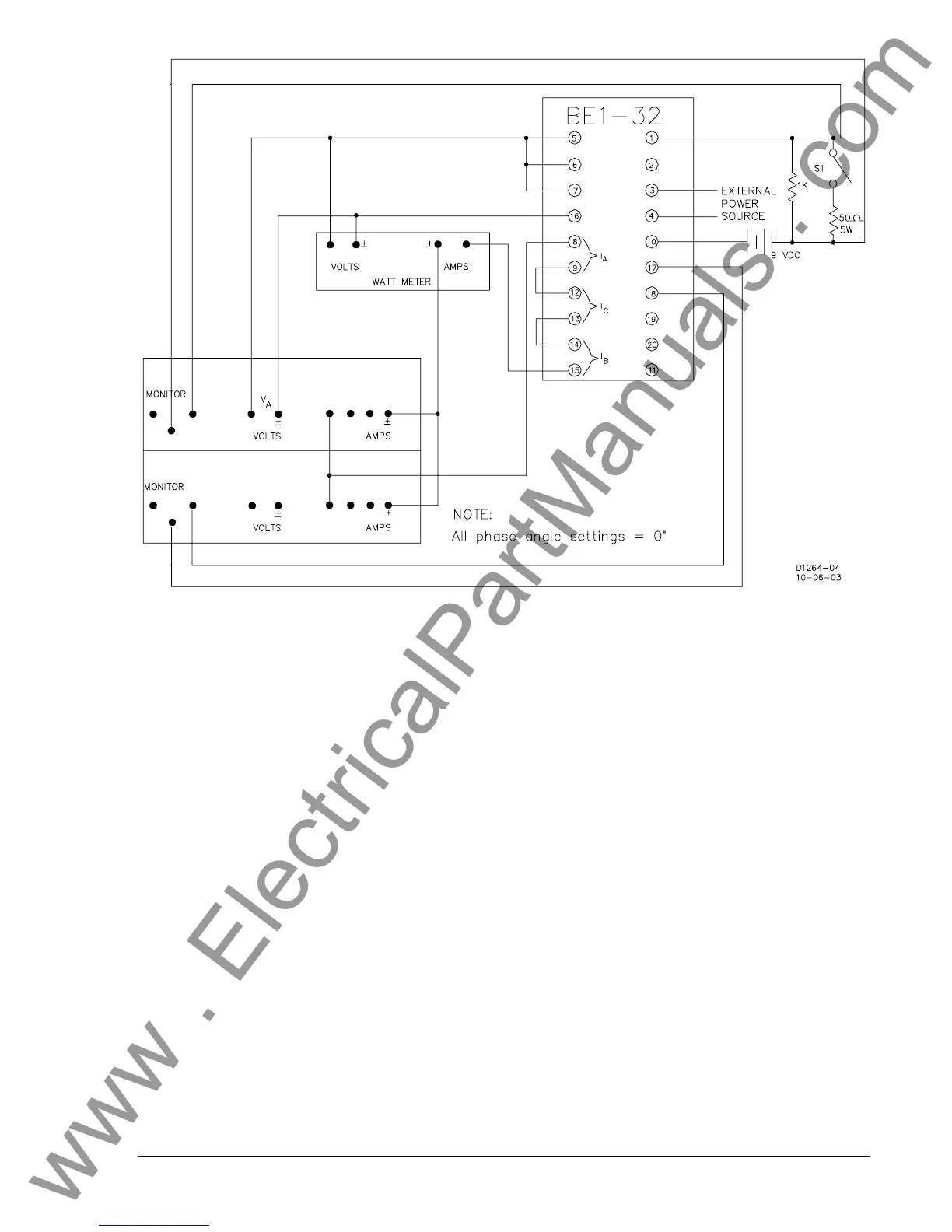
1. Type D sensing is calibrated in three-phase watts using single-phase sensing inputs. Using the test connections
shown, the relay may be calibrated in true three-phase power using one-third of the pickup current corresponding
to the desired overpower or underpower pickup in watts. Adjust the relay test set to produce this current value
from the following equation.
IVW
A
××= 3
W is the desired pickup in watts.
V is the applied voltage.
I is the applied current.
With a wattmeter, W is determined by the following equation.
Reading WattmeterW ×= 3
2. Terminals 1 and 10 are the overpower trip output device connections for both BE1-32R and BE1-32O/U.
Terminals 2 and 10 are the underpower output connections for the BE1-32O/U.
3. Terminals 17 through 20 are auxiliary output contacts. Determine the auxiliary output contact configuration by
referring to the relay style number.
Figure 5-4. Type D Sensing Test Connections
www . ElectricalPartManuals . com