9469200995 13-19
DGC-2020ES BESTlogic™Plus
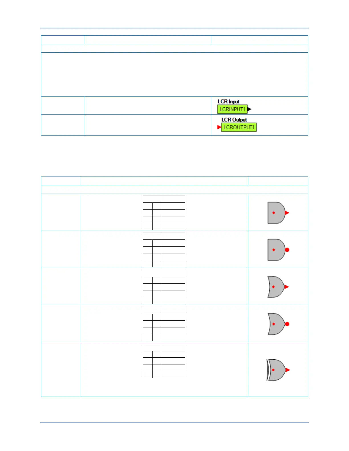
The logic control relays (LCR) consist of LCR outputs and LCR inputs. The output can be used to terminate the
“output” end of a logic network, and then use the corresponding input as an input to logic elsewhere in the logic
scheme. When a given LCR output is true the corresponding LCR input is true. In other words, when LCR Output
N (N being a number from 1 to 16) becomes true, then LCR Input N is true also.
If you get a “too many logic levels” error while building a logic network, LCR outputs and inputs can be used as a
solution to this problem. Place an LCR output on the end of the partial logic network and then use the
corresponding LCR input to build more logic than was previously possible.
Input 1-16
Output 1-16
Components
This group contains Logic Gates, Pickup and Dropout Timers, Latches, and Comment Blocks. Table 13-2
lists the names and descriptions of the objects in the Components group.
Table 13-2. Components Group, Names and Descriptions
When an XOR gate has more than two inputs, the output is true
whenever an odd number of inputs are true.


 To Next Page