Camera Link Implementation AW00118702000
2 Basler racer Camera Link
All camera models implement the "base", "medium", and "full" configurations as defined in the
Camera Link standard. Individual differential line transmitter circuits support the respective Camera
Link configurations: Transmitter X supports the base configuration, transmitter Y partly supports the
medium configuration and partly the full configuration, and transmitter Z supports full configuration.
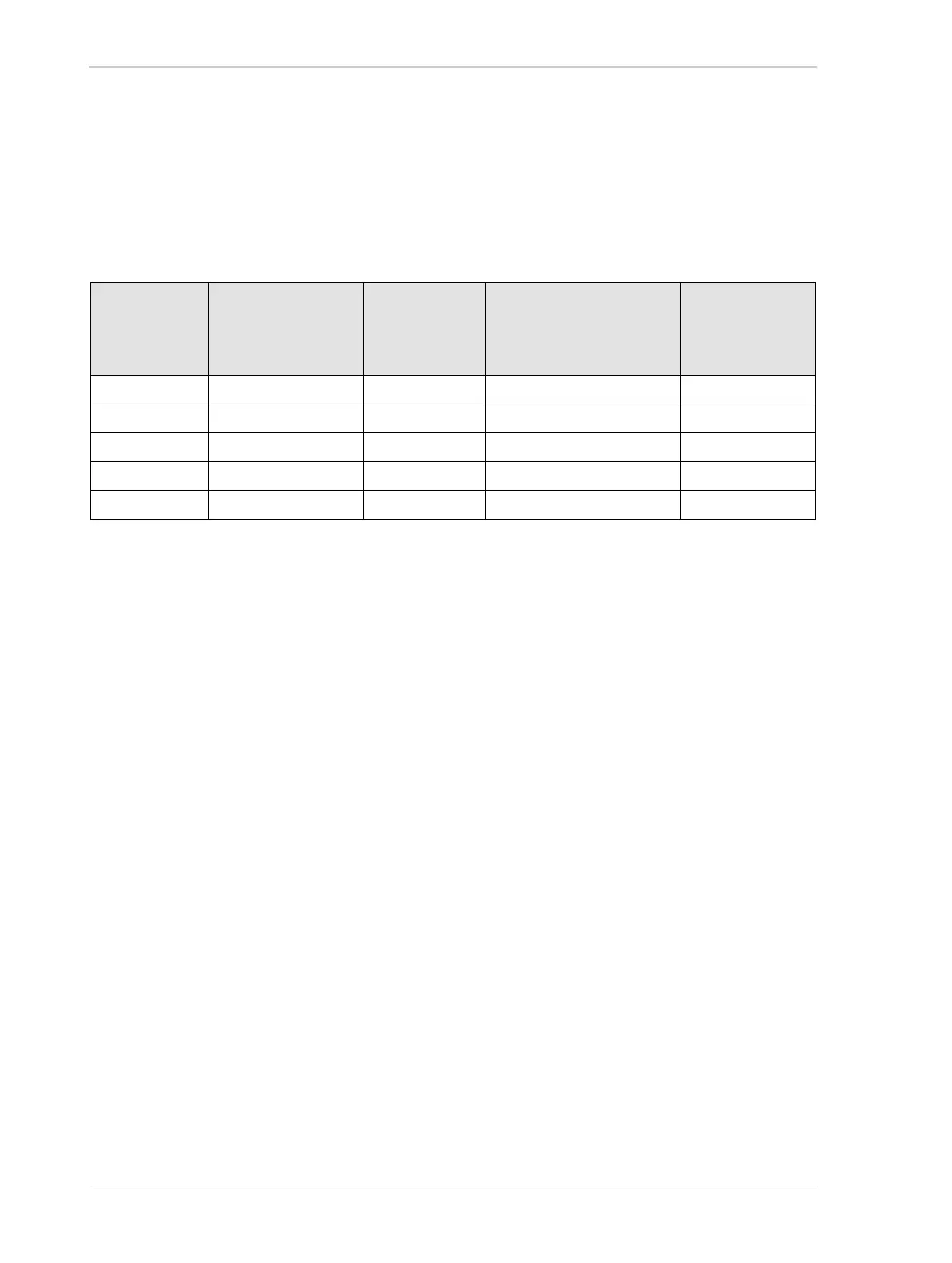
The determination of whether a camera will operate in the base, medium, or full configuration
depends on the camera’s current tap geometry setting as shown Table 1.
1.2 SDR Connector Pin Assignments and
Numbering
Two 26-pin, 0.03” pin spacing, Shrunk Delta Ribbon (SDR) female connectors are used on the
camera. The pin assignments and pin numbering for the base connector are as shown in Table 2
and for the medium/full connector are as shown in Table 3 on page 4.
Camera Link
Tap Geometry
Setting
Available Pixel Bit
Depths for Mono
Cameras
Camera Link
Configuration
Camera Link Connectors
Used to Transmit Data
Camera Link
Transmitters
Used to Transmit
Data
1X 8 bit, 10 bit, 12 bit Base Base Only X
1X2 8 bit, 10 bit, 12 bit Base Base Only X
1X4 8 bit, 10 bit, 12 bit Medium Base and Medium/Full X and Y
1X8 8 bit, 10 bit Full (Octo) Base and Medium/Full X, Y, and Z
1X10 8 bit Full (Deca) Base and Medium/Full X, Y, and Z
Table 1: Camera Link Details at Various Tap Geometry Settings

 Loading...


