AW00118702000 Camera Link Implementation
Basler racer Camera Link 3
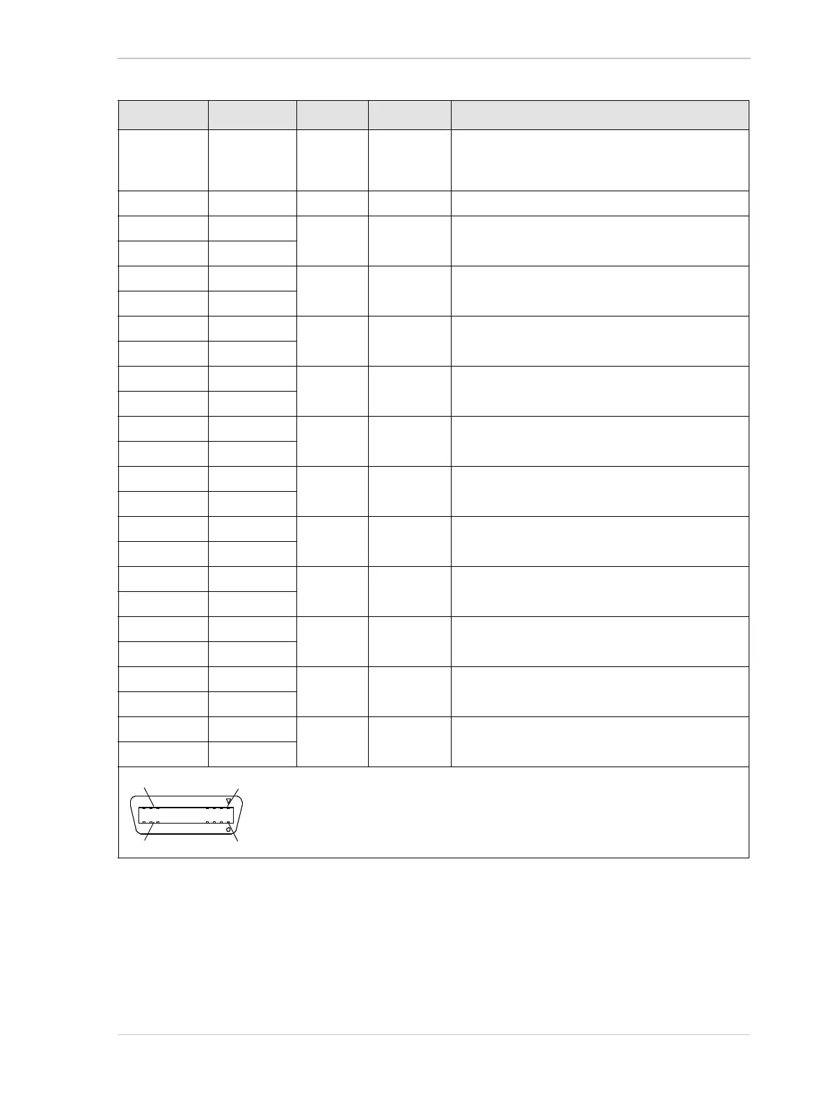
Pin Number Signal Name Direction Level Function
1, 26 * Cam Pow. In +12 VDC Camera power, +12 VDC nominal, < 1% ripple. For
more details about PoCL power requirements see
the Camera Link specifications v. 2.0 and above.
13, 14 ** Power Ret. Return
Camera power return (Gnd)
2 X0- Output Camera Link
LVDS
Data from transmitter circuit X
15 X0+
3 X1- Output Camera Link
LVDS
Data from transmitter circuit X
16 X1+
4 X2- Output Camera Link
LVDS
Data from transmitter circuit X
17 X2+
6 X3- Output Camera Link
LVDS
Data from transmitter circuit X
19 X3+
5 XClk- Output Camera Link
LVDS
Pixel clock from transmitter circuit X
18 XClk+
7 SerTC+ Input RS-644
LVDS
Serial communication data receive
(SerTC = "serial to camera")
20 SerTC-
8 SerTFG- Output RS-644
LVDS
Serial communication data transmit
(SerTFG = "serial to frame grabber")
21 SerTFG+
9 CC1- Input RS-644
LVDS
Configurable
22 CC1+
10 CC2+ Input RS-644
LVDS
Configurable
23 CC2-
11 CC3- Input RS-644
LVDS
Configurable
24 CC3+
12 CC4+ Input RS-644
LVDS
Configurable
25 CC4-
* Pins 1 and 26 are tied together in the camera.
** Pins 13 and 14 are tied together in the camera.
Table 2: Pin Assignments and Numbering for the Base Configuration 26-pin SDR Connector

 Loading...


