S
4 SETUP OF THE SEPARATOR
4.1 INSTALLATION DIAGRAM
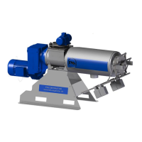
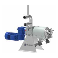
4.2 CONDITION OF THE FAN PRESS SCREW SEPARATOR UPON DELIVERY
The FAN PSS was developed by the company FAN Separator GmbH. The separator is delivered as a
unit, including installed electric motor, on a pallet. The inflow T-piece and the ventilation pipe are en-
closed separately for easier transport and must be installed before the initial start-up.
You must connect the geared motor and the vibrator (if included) of the separator to the power supply
of the optionally available switch cabinet and connect this to the electricity supply. It is recommended
that the corresponding electrical control for the separator or for the separator and the FAN submersed
motor pump be purchased from FAN since it will be already adapted to the corresponding drive mo-
tors.
Connecting the supplied hoses, if included, to the inflow and discharge connections of the machine
completes the installation of the FAN press screw separator.
Work on electrical and electronic components of the system may only be per-
formed by a trained electrician or otherwise appropriately trained personnel under
the guidance and supervision of a trained electrician in accordance with the ap-
plicable electrical and electronic regulations.
4.3 REQUIRED TOOLS
Special tools are not required for setting up the FAN press screw separator.
Standard tools for assembly and electrical tools are required for assembly, setup and disassembly.
The customer must check based on the dimensions and weight of the separator whether the available
lifting equipment (forklift, tractor with front loader, crane with corresponding belts or chains) is sufficient
for setting up the separator.