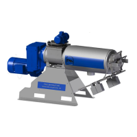
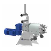
Operating Manual for FAN Press Screw Separator 1.2/3.2/3.3/5.2
No solids are produced
No liquid is discharged
Separator is running
1. The material supply has been in-
terrupted:
The pump is off
T-piece at the inflow or ventilation
opening blocked; a siphon effect
occurs [“overflow line is complete-
ly filled”]; the outlet of the overflow
line is submersed in the liquid.
Clogged / restricted effluent line
2. The auger is turning clockwise.
3. The rotation direction of the pump
is incorrect, the supply line is vi-
brating
4. Long fibers (stray, plastic fiber etc.)
are blocking the liquid transport
1. Check: Switch cabinet and overflow
line.
Inspect and start the pump.
Clean the lines. Install a ventilation
pipe with a larger cross-section; re-
duce the pump capacity; ensure
that the overflow line is clear.
Ensure that the liquid can drain
freely.
2. Swap the two phases of the elec-
tricity line so that the auger turns
counter-clockwise.
3. Change the rotation direction of the
pump.
4. Replace the cutting blade in the
pump cutting unit.
Solid discharge too low
Effluent discharge too low
(lower than is typical for this
medium)
Separator is running
1. Pump capacity (feed rate) is too
low – no overflow in the bypass
line
2. Lifting effect in the overflow line,
the medium is being drawn out of
the separator
3. Too many weights in place or too
much contact pressure
4. Excess wear on the screen or au-
ger
5. Screen positioned incorrectly or
clogged;
6. Auger channels clogged
7. Screen only worn in certain places,
guide rails for the screen not set
correctly
8. Medium is pumped / stirred too
much (ground fine)
1. Inspect pump (rotation direction)
and/or control the pump capacity.
Check the transport line.
2. Affix the ventilation valve / pipe to
the T-piece of the separator.
Reduce the feed rate so that the
overflow pipe is no more than half
full. Ensure that the overflow can
flow out freely.
3. Remove two weights or reduce the
leverage of the weights.
4. Check the auger diameter, check
the screen for wear. Replace the
screen and auger, if necessary.
5. Clean the screen through the side
windows or remove it for cleaning, if
necessary.
Activate the reverse direction con-
trol.
6. Clean the auger, contact the FAN
company concerning possible
changes to the inflow of the separa-
tor.
7. Check the guide rails for soiling /
clogging
8. Install a buffer container at the
inflow.
Solid discharge is very low
Effluent discharge is normal
Separator is running
1. The solid portion in the inflow is
very low
2. The gap width of the screen is too
large
1. Add some solid to the inflow.
2. Install a screen with a smaller gap
width. The available screen gap
widths are: 0.1, 0.25, 0.35, 0.50,
0.75, and 1.25 mm. After changing
the gap width, accustom yourself
to a change in the “normal” operat-
ing condition.