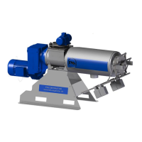
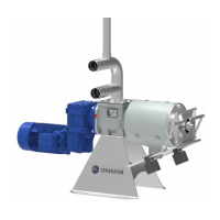
Operating Manual for FAN Press Screw Separator PSS 1.2/3.2/3.3/5.2
If no FAN pump is installed, the pump for supplying the separator should have a pump
rate of at least 35 m³/h for PSS1.2-520/PSS3.2-520/PSS5.2-520 (50 m³/h for PSS1.2-
780/PSS3.2-780/PSS3.3-780/PSS5.2-780 and 70 m³/h for PSS3.2-1040/PSS 5.2-1040 )
since the capacity of the separator otherwise cannot be fully utilized. To keep pressure
losses due to pipe friction low, the pipes should have a diameter of at least 100 mm (4").
5 ELECTRICAL CONNECTION
The electric motor is equipped with a terminal strip. Like all electrical connections, the external motor
control must be connected properly by a qualified electrician.
Work on electrical and electronic components of the system may only be per-
formed by a trained electrician or otherwise appropriately trained personnel under
the guidance and supervision of a trained electrician in accordance with the ap-
plicable electrical and electronic regulations.
Fuses do not protect the motor from overloads; they only protect the electrical
supply lines or switching systems from damage in event of a short-circuit.
The electric motor must always be protected with a motor protection circuit breaker that must be set to
the rated current shown on the type plate depending on the motor wiring. Only motor protection circuit
breakers certified according to the following standards may be used: IEC, UL, CSA.
Set the motor protection circuit breaker to the correct value, never above the max.
rated current according to the type plate.
It is recommended that the corresponding electrical control for the separator or for the separator and
the submersed motor pump be purchased from FAN since it will be already adapted to the correspond-
ing drive motors.
Ensure the correct rotation direction of the auger shaft when making the electrical
connection!
In forward motion, the auger shaft turns counter-
clockwise
(as viewed from the output regulator toward the geared
motor).
If this is not the case, two of the current-carrying conduc-
tors at the geared motor connection or in the switch cabi-
net must be swapped.
Fig. 5-1 Rotation direction of the auger