The separator must be set up so that the solid can be freely
discharged. There must be a corresponding height difference
between the solid discharge point and the ground. The volume
of the cone of discharged material can be determined based on
the setup height.
The overflow line for the raw medium as well as the drainage
line of the separated medium should drain without pressure into
the corresponding storage tanks.
The overflow line should be run without a “siphon” in order to
avoid a lifting effect and to ensure good separator throughput
(see also section 14 “Problems - Troubleshooting”).
Avoid winding, dipping and twisting of the pipeline and use tub-
ing that is resistant to negative pressure.
4.8.1 Standard Setup
With the standard execution of inflow – oscillator with inflow tube –
the inflow tube DN100 is vertically integrated in the inflow flange.
(separator housing on top)
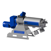
For supply with a pump, see Fig. 4.8, a T-piece available on option
must be connected with the vertical inflow tube. The supply line is
connected to the T-piece on top. To do so, you need a hose di-
mensioned DN100. Coupling pieces for the hose lines as well as
bows are available as accessories.
The overflow line is connected to the T-piece laterally. To do so,
you also need a hose dimensioned DN100.
The ventilation tube is to be mounted to the overflow line at the T-
piece. It avoids an underpressure in the separator when the medi-
um makes a vacuum in the return line.
The ventilation pipe shall project the supply and/or the overflow line
by approx. 1,5 m. Connection: 1 ½” external thread.
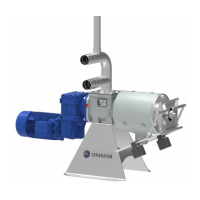
It is also possible to mount two T-pieces available on option, see
Fig. 4.9. The supply line is connected to the bottom T-piece lateral-
ly. The overflow line is connected to the top T-piece laterally and
the vertical line is used for ventilation. (To do so, you also need
hoses dimensioned DN100.)
For supply from an elevated tank, see Fig. 4.10, the supply line is
connected directly to the inflow tube with a hose DN100. In this
case, no overflow is needed, however, a ventilation tube must be
mounted in the supply line.
4.8.2 Alternative Setup
Alternatively an oscillator with hopper (Fig. 4-11) or only a big hop-
per (Fig. 4-11) can be mounted on the supply side. These compo-
nents are available on option.
In this case neither an overflow line nor a ventilation line is needed.
4.8.3 Drainage Line
The drainage line is connected to the outlet tube DN100(PSS1.2-
520, PSS1.2-780, PSS5.2-520) DN125(PSS3.2-520,PSS3.2-780,
PSS3.2-1040,3.3-780,PSS5.2-780,PSS5.2-1040) DN125 on the bot-
tom of the separator housing. (see Abb.4-12)