6.4.3 Identifying label
Important
The identifying label (7221476-01) supplied with the outdoor sen
sor must be signed and affixed on or adjacent to the boiler. The
label must be readily accessible without removing the boiler cas
ing or any other disassembly. This label is required to enable SAP
and energy assessors to identify that a weather compensation de
vice is installed and connected .
6.4.4 Outdoor sensor graph
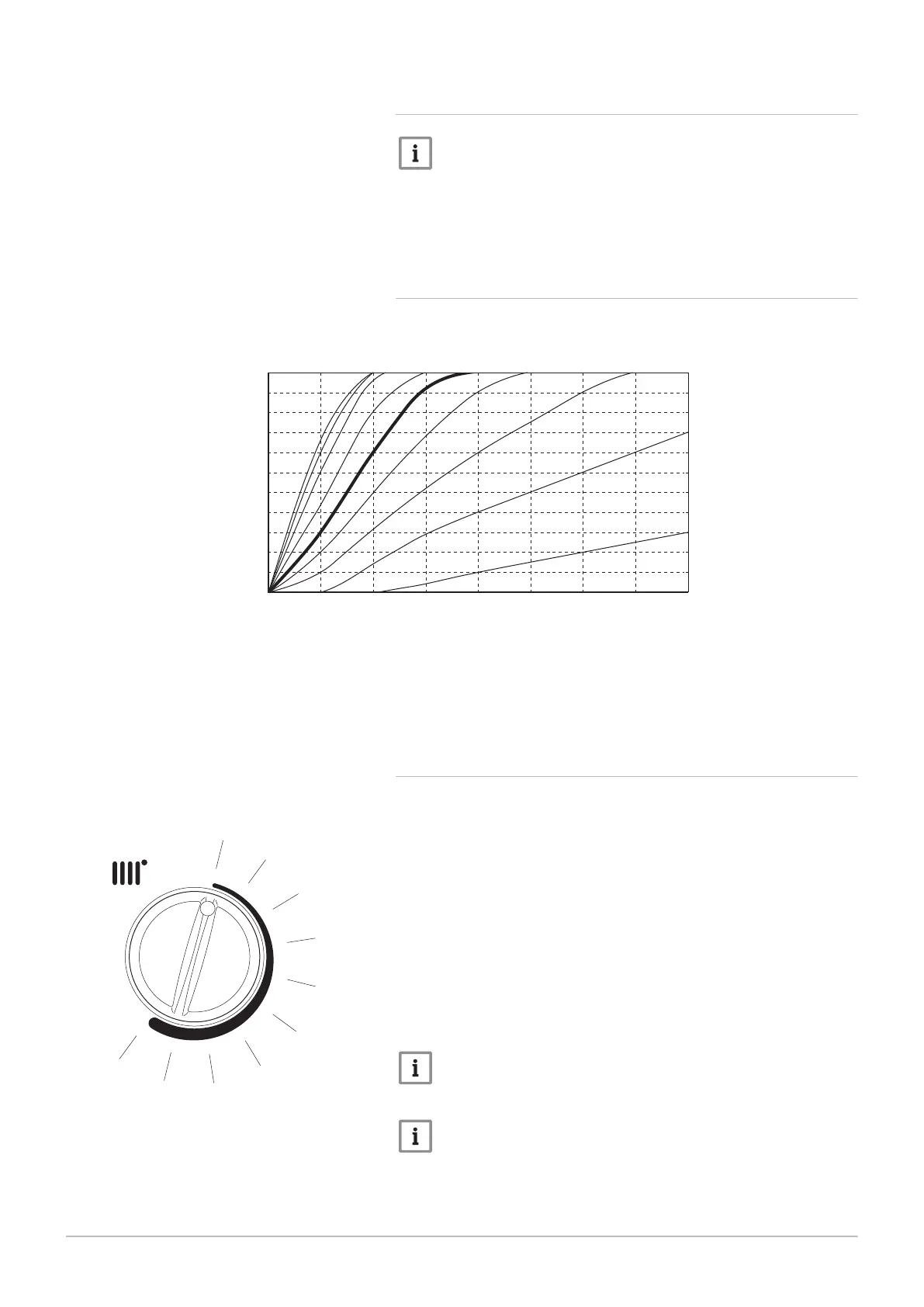
Fig.39 Graph showing available curves
PN-0000627
20°
30°
35°
40°
45°
50°
55°
60°
65°
70°
75°
80°
85°
90 80 70 60 50 40 30
20
10
00
15° 10° 5° 0° -5° -10° -15° -20°
There are 9 available curves. It is essential that expected outdoor temper
atures and the user requirements are considered before selecting the
curve.
Boiler flow temperature is shown on the vertical axis. The outside tempera
ture is along the horizontal axis.
6.4.5 Setting outdoor sensor curve
1. Ensure that there is power to the boiler (though it is not necessary
for there to be any heating demand).
2. The central heating control knob should be turned clockwise to the
position which corresponds with the desired curve as shown on the
graph.
3. Curve 50 is recommended as the most suitable for the normal range
of conditions expected in the UK. Consider the type of dwelling and
discuss with the user their requirements — one of the other curves
may be more appropriate.
4. Normally the display will show the current temperature of the water
in the boiler. As the knob is turned the display will show the selected
curve.
5. Once the curve is set the installation and commissioning of the boil
er can be completed.
Note
Explain to the user how to select a different temperature curve
and how the outdoor sensor regulates the boiler flow temperature.
Important
When an OpenTherm controller is connected adjustment of the
boiler, e.g. heating temperature, is made using the OpenTherm
controller rather than the boiler controls. The boiler controls are
overridden by the OpenTherm control. Please check the function
ality with the manufacturer of the OpenTherm controller.
Fig.40 Control knob and setting curve
Mi
n
Max
00
10
20
30
40
50
60
70
80
90
PN-0000628
6 Installation
7679306 - 1 - 10082017 45
 Loading...