essary. Carrying and lifting equipment should be used as required. e.g.
when install in a loft.
5.5 Unpacking & initial preparation
5.5.1 Unpacking
Caution
RISK ASSESSMENT - Before commencing the installation it is
recommended that the "Five Steps to Risk Assessment" docu
ment published by the HSE is consulted, and an assessment per
formed as described. GAS SUPPLY - The gas supply, gas type
and pressure must be checked for suitability before connection.
See
Handling, page 9 before unpacking or lifting the boiler.
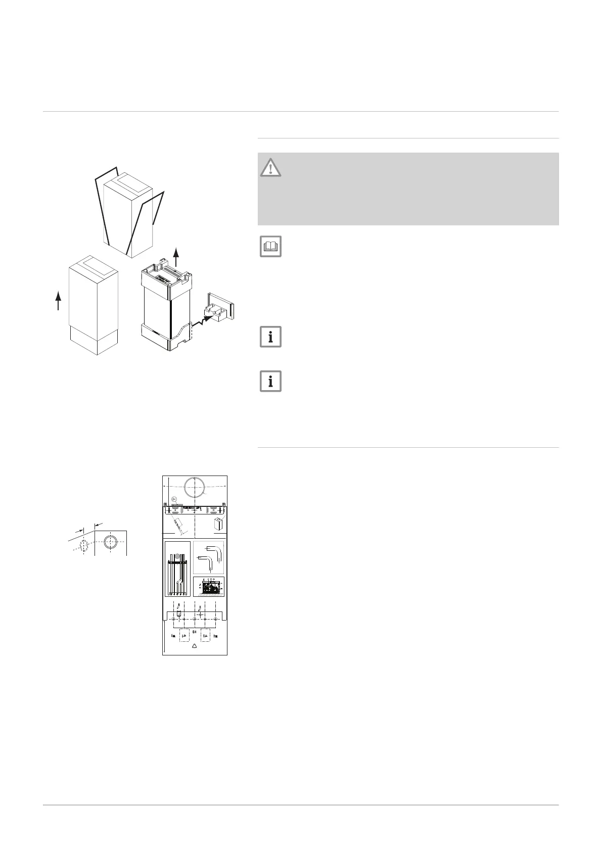
To unpack the boiler:
1. Remove the banding and the cardboard sleeve.
2. Remove the polystyrene top piece and installation kit.
3. Snap off the rear part of the polystyrene bottom piece.
Important
Polystyrene base should be removed completely if fitting the boiler
into a space with minimum side clearances of 5 mm each side.
Important
If removing the polystyrene base, the sealing caps can also be re
moved at this stage. Care must be taken to avoid damage from
any residual water in the boiler.
5.5.2
Initial preparation
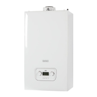
1. After considering the site requirements position the fixing template
on the wall ensuring it is level both horizontally and vertically.
2. Mark the position of the two most suitable fixing slots for the wall
plate.
3. Mark the position of the centre of the flue hole (rear exit). For side
flue exit, mark as shown.
4. If required, mark the position of the gas and water pipes. Remove
the template.
5. Cut the hole for the flue (minimum diameter 116mm).
6. Drill the wall as previously marked to accept the wall plugs supplied.
Secure the wall plate using the fixing screws.
7. Using a spirit level ensure that the plate is level before finally tight
ening the screws.
Fig.23 Unpacking the boiler
Fig.24 Template
PN-0000346
150 mm
Ø 8mm
50mm MIN
Heating
Return
(22mm)
Gas
(22mm)
Heating
Flow
(22mm)
Hot Water
Outlet
(15mm)
Combi Only
Not System
Cold Water
Inlet
(15mm)
Combi Only
Not System
Clearance above 178mm
Clearance below
200mm
7664094-02
Ø 22mm
Condensate
Drain
Pressure
Relief
Side Clearance 5mm
Side Clearance 5mm
195.5mm 195.5mm
65mm 65mm 65mm 65mm
22mm CH F & R
22mm Gas
This leg into tap
15mm DHW
In/Out
This leg into tap
Pipe Profiles. (Where copper tails are not supplied with the boiler)
To ensure that the vertical pipework is at the optimum distance (whether
piping up or down) make up in accordance with these exactly sized profiles.
View from
under boiler
Safety Pressure Relief
Condensate
Primary Drain
Wall
116mm Dia Minimum
Aperture For
Flue Tube
Pipework run to rear of boiler.
If it is desired to route pipework vertically behind the boiler the
5 position clip bracket must be used. This guides the gas pipe
and one of the DHW pipes to one side of the flue. They may be
set to the right or left. To engage in the bracket the gas pipe must
be offset by 70mm and the DHW by 35mm. Compression fittings
cannot be used behind the boiler. The use of 90
o
elbows is not
recommended. The clip bracket is retained using the same screws
that fasten the wall plate in position. DO NOT ROUTE THE PRV
OR CONDENSATE DISCHRGE UPWARDS !
Clip
Bracket
5 Before installation
36 7679306 - 1 - 10082017



 To Next Page