6 Installation
6.1 General
Installation must be carried out in accordance with the prevailing regula
tions, codes of practice and the recommendations in this manual.
Danger
If the boiler is installed in a compartment do not use it for storage
purposes. Do not obstruct any purpose provided ventilation open
ings.
Caution
Where the boiler is sited in an unheated enclosure provision must
be made to protect against frost, e.g. frost thermostat, pipe ther
mostat.
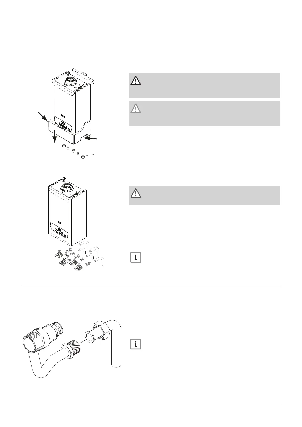
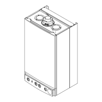
1. Lift the boiler by gripping "a" and "b" and hook the boiler onto the wall
plate.
2. Remove the polstyrene bottom piece by slipping it off downwards.
3. Remove the sealing caps from the boiler connections under the boiler
(including the condensate trap).
c Sealing caps
Warning
Some residual water may escape when removing the sealing
caps. Take precautions to avoid damage to components !
4. Remove the taps, elbow and sealing washers from the fitting kit. The
taps and elbow accept the 15mm or 22mm copper tails supplied.
5. Using the sealing washers provided connect the appropriate tap to the
heating flow and return, gas supply and mains cold inlet. Connect the
elbow to the DHW flow outlet.
6. Always fit the tap with the drain point to the heating flow.
7. Ensure all joints are tight.
Important
Connect the pressure relief discharge pipe first before any other
pipework.
6.2 Assembly
6.2.1 Fitting the pressure relief discharge pipe
1. The valve and discharge pipe are assembled to the boiler, terminat
ing in a threaded male coupling.
2. Determine the routing of the discharge pipe in the vicinity of the boil
er. Make up as much of the pipework as is practical, including the
15mm elbow and nut supplied.
Important
Make all soldered joints before connecting to the pressure relief
valve. Do not adjust the position of the valve. The discharge pipe
must be installed before pressurising the system.
3. The pipework must be at least 15mm diameter and run continuously
downwards to a discharge point outside the building.
4. Complete the discharge pipework and route it to the outside dis
charge point.
5. The pipework must be clipped at suitable intervals to support it, com
mencing as close to the boiler as possible.
Fig.28
Mounting the boiler
Fig.29
Fig.30 Pressure relief pipe connection
6 Installation
7679306 - 1 - 10082017 39



 To Next Page