7.3 Commissioning procedure
7.3.1 De-Aeration function
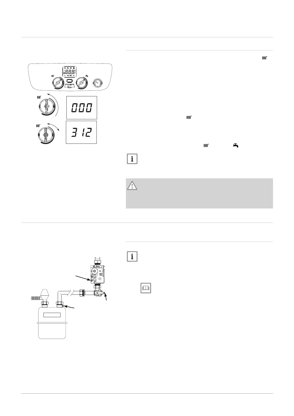
Before turning on the power to the boiler, rotate the CH control knob ( )
fully anticlockwise.
The purpose of the function is to remove as much air as possible from the
heating system. To assist this it is essential that all precautions are taken
to remove air manually before enabling the function. Ensure that all radia
tors are fully bled, starting on the lowest floor in properties of more than
one storey. Any high points in the system should be fitted with a suitable
venting device. On the boiler’s first power up de-aeration lasts approxi
mately 7 minutes. The boiler will not operate during this process.
1. Turn on the power to the boiler. The display shows "000" .
2. Turn the CH control knob ( )
1
/
4
turn clockwise twice in quick succes
sion (within 2 seconds).
3. Display shows "312" while de-aeration is taking place (approximately
7 minutes).
4. When de-aeration has completed, the display will show the primary
flow temperature and both the CH ( ) and DHW ( ) symbols.
Important
If during the first commissioning process the power to the boiler is
interrupted the de-aeration function will re-start automatically at
the point which it stopped once power is restored.
Caution
If the system is drained in the future (even partly, when replacing
a radiator for example) the de-aeration function must be repeated.
Also the inhibitor concentration must be checked and replenished
if necessary.
7.4
Gas settings
7.4.1
Check the operational (working gas inlet pressure and
gas rate)
Note
If the pressure drops are greater than shown in the diagram oppo
site, a problem with the pipework or connections is indicated. Per
missible pressure drop across system pipework ≤ 1mbar. Carry
out chimney sweep.
See
Checking combustion - chimney sweep mode, page 49.
Fig.42 Setting de-aeration
M
a
x
M
i
n
R
M
a
x
M
i
n
R
x 2
PN-0000608
R
Reset
bar
0
1
2
3
4
M
i
n
M
a
x
M
a
x
M
i
n
Fig.43 Gas meter to valve
EV1
EV2
P. OUT
1 2 3 4
VENT
RQ
ADJ.
17-21 mbar
PN-0000361
19-23 mbar
18-22 mbar
A
7 Commissioning
48 7679306 - 1 - 10082017



 To Next Page