33
71.07144.01 - EN
INSTRUCTIONS FOR FITTERS
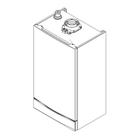
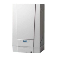
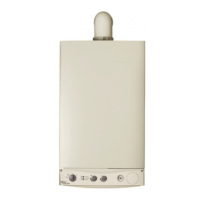
14. INSTALLING THE BOILER
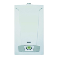
15. DIMENSIONS OF BOILER
Figure 5
24 24 F
CG_2009 / 0912_1004
CG_2009 / 0912_1005
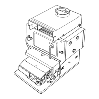
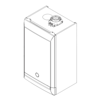
After deciding the exact location of the boiler, x the template to the
wall.
Connect the system to the gas and water inlets present on the lower bar of
the template. Fit two G3/4 taps (delivery and return) on the central heating
circuit; these taps make it possible to carry out important operations on
the system without draining it completely. If you are either installing the
boiler on an existing system or replacing one, as well as the above, t a
settling tank under the boiler on the system return line in order to collect
any deposits and scale circulating in the system after ushing. After xing
the boiler to the template, connect the ue and air ducts, supplied as
accessories, as described in the following sections.
If the model 24 natural draught boiler is installed, connected it to the ue
with a metal pipe resistant to normal mechanical stress, heat, products
of combustion and relative condensate.
Figure 4
24 F - 24
CG_2011 / 0912_1003
G”3/4 HEATING DELIVERY
G”3/4 HEATING RETURN
G”1/2 DOMESTIC HOT WATER OUTLET
G”1/2 DOMESTIC COLD WATER INLET
G”3/4 GAS INLET TO BOILER
WARNING
Carefully tighten the water connections to the nipples of the boiler (maximum tightening torque 30 Nm).
 Loading...