47
71.07144.01 - EN
INSTRUCTIONS FOR FITTERS
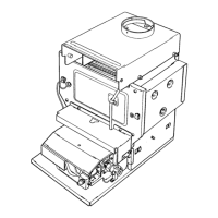
29. FUNCTIONAL CIRCUIT DIAGRAM
24 F
Legend:
1 NTC domestic hot water sensor
2 Boiler drain tap
3 Boiler lling tap
4 Water pressure switch
5 Gas valve
6 Gas train with injectors
7 Water-fumes exchanger
8 Fumes conveyor
9 Fan
10 Positive pressure point
11 Negative pressure point
12 Air pressure switch
13 Central heating NTC sensor
14 Safety thermostat
15 Ignition / ame detection electrode
16 Burner
17 Expansion vessel
18 Pump and air separator
19 Pressure gauge
20 Safety valve
21 Automatic by-pass
22 DHW priority sensor
Figure 17
CG_2110 / 0902_0607
Heating
delivery
DHW
outlet
Gas DHW
inlet
Heating
return
 Loading...