36
71.07144.01 - EN
INSTRUCTIONS FOR FITTERS
… SEPARATE FLUE AND AIR DUCTS
This type of installation makes it possible to discharge exhaust fumes both outside the building and into single ue ducts.
Comburent air can be drawn in at a different location from that of the ue terminal. The splitting kit comprises a ue duct
adaptor (100/80) and an air duct adaptor. For the air duct adaptor, t the screws and seals previously removed from the cap.
The 90° bend allows the boiler to be connected to a ue-air duct in any direction as it can be rotated by 360°. It can also
be used as a supplementary bend combined with a duct or a 45° bend.
• A90°bendreducestotalductlengthby0.5metres.
• A45°bendreducestotalductlengthby0.25metres.
WARNING
The boiler inlet and outlet ducts (C52) must comply with the following maximum lengths:
- inlet duct: Lmax= 8m
- outlet duct: Lmax= 15m
Therst90°bendisnotincludedwhencalculatingthemaximumavailablelength.
Boiler
model
(L1+L2)
Position
of air regulator
Flue
RESTRICTOR
A
CO
2
%
G20 G31
24 F
0 ÷ 4
A
NO 6,4 7,14 ÷ 14
B
14 ÷ 23
C
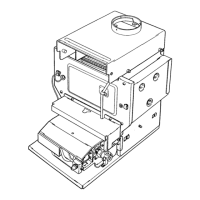
Adjusting the air regulator for sepa-
rate flues
This regulator must be adjusted to
optimise combustion efficiency and
parameters. After turning the air intake
connecter, which can be mounted both
to the right and the left of the exhaust
flue duct, suitably adjust the excess
air according to the total length of the
combustion exhaust and inlet ue ducts.
Turn this regulator counter-clockwise
to decrease the excess of comburent
air and vice-versa to increase it. To ne
tune, use a combustion product analyser
to measure the amount of CO2 in the
fumes at maximum heat capacity, and,
if a lower value is measured, gradually
adjust the air regulator until the amount
of CO2 indicated in the following table is
measured. To mount this device correct-
ly, consult the relative instructions.
Figure 8
Flue duct adaptor
Connector
Air intake restrictor
CG_2114 / 0902_2801
 Loading...