Chapter 2: Routine Maintenance
Advisor
®
Service Manual 2-5
CO
2
HILO Calibration
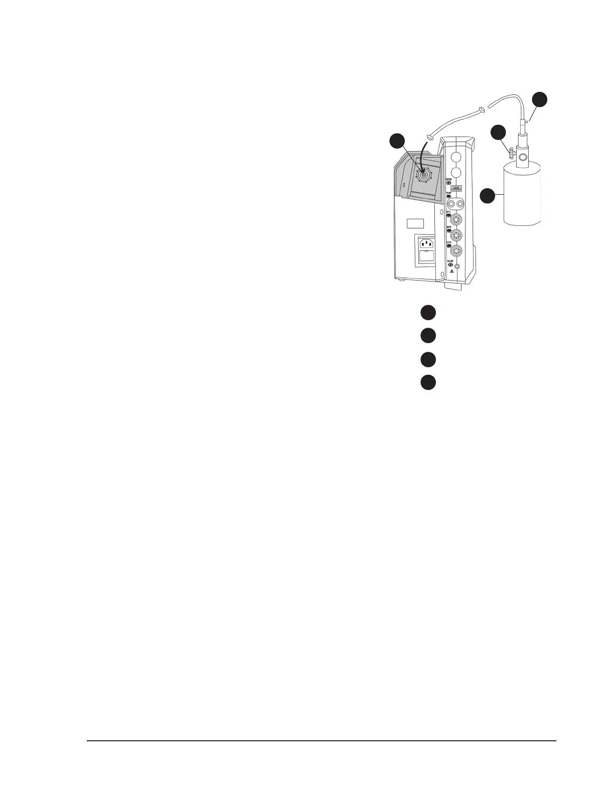
Figure 2.2: HILO CAL
NOTE! A HILO CAL procedure should be performed after the
capnography parameter has been on for at least 15
minutes.
NOTE! Remove the device from the patient before performing a
high/low calibration procedure.
To perform a HILO CAL:
If the patient is attached to the capnography module, disconnect 1.
the sample line tubing from the monitor by unscrewing the lter
luer from the module on the left side of the monitor.
If you are using a standard pneumatics module, remove the 2.
moisture lter and attach the calibration adapter (BCI
®
part
number 8223) to the gas inlet.
Connect one end of the “T” assembly to the regulator on the gas 3.
canister. Connect the second end of the “T” assembly to the gas
inlet on the monitor. Leave the third end of the “T” assembly open
to room air.
Turn the rotary knob on the monitor to move the cursor. Highlight 4.
the CO
2
parameter box name and push the knob to select.
Highlight HILO CAL and push the knob to select.5.
Turn the rotary knob to highlight YES and push the knob to select. 6.
TURN GAS ON will be displayed in the CO
2
parameter box.
Quickly open the ow control valve on the calibration gas canister. The valve must be fully opened in less 7.
than 30 seconds.
When TURN GAS OFF is displayed in the CO8.
2
parameter box, close the ow control valve of the calibration
gas canister.
When the calibration procedure is nished, CAL DONE will be displayed in the CO9.
2
parameter box.
Change the units of measurement for CO10.
2
to percent concentration (%) as follows.
Turn the rotary knob on the monitor to move the cursor. On the main menu at the bottom of the display, a.
highlight SETUP and push the knob to select.
Highlight b. PARAMETER OPTIONS and push the knob to access the parameter options submenu.
Highlight c. CO2 UNITS and push the knob to select.
Highlight the desired unit and push to select.d.
Highlight e. MAIN or PREVIOUS and push the knob to select.
Verify the accuracy of the calibration by opening and closing the ow control valve on the calibration gas 11.
canister at a rate approximately 15 Hz (on for two seconds, o for two seconds). Repeat this for 4-8 on/o
cycles.
Verify that the ETCO12.
2
reading in the CO
2
parameter box indicates 10.0% CO
2
0.4 (9.6-10.4%)
Disconnect the calibration gas xture. If you are using a standard pneumatics module, remove the 13.
calibration adapter and reconnect the moisture lter.
If the calibration procedure is unsuccessful, a message will be displayed in the CO•
2
parameter box. The
capnography parameter will revert to the last successful calibration data and resume operation.
4
1
2
3
Gas inlet
T connector
Calibration gas
Flow control valve
4
1
2
3