S2510-B Hardware Installation Manual
- 10 -
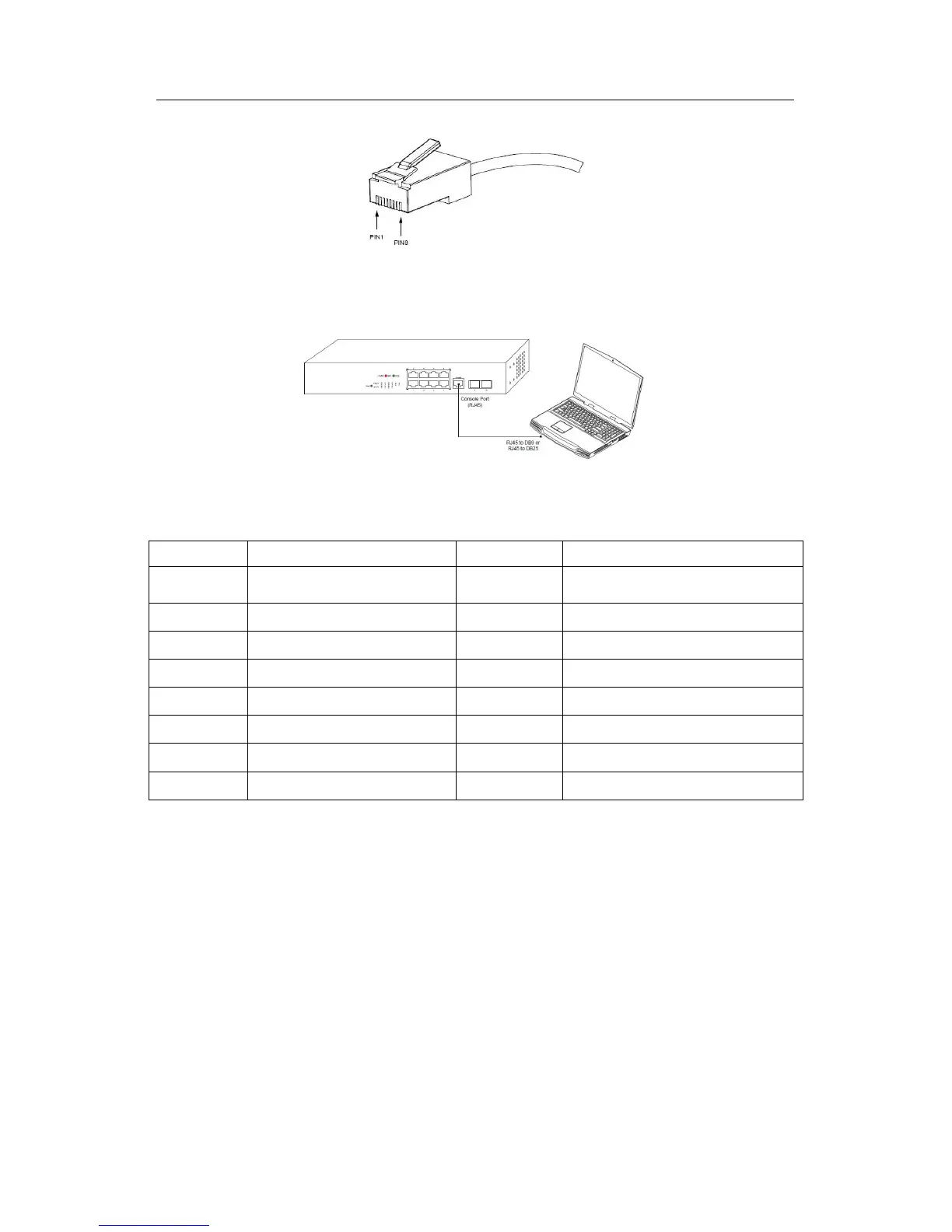
Figure 3- 3 RJ-45 connector of the console port
Figure 3- 4 Connecting the console port of S2510-B and a computer
Table 3- 1 Definition of the pins of the console port
Note:
Because the console port of S2510-B bears no flow control, you need to set Data flow
control to none when using a superior terminal to manage S2510-B configurations, or
the single-pass problem will arise from the superior terminal.
The cable is used to connect the console port of the S2510-B switch and the outside
console terminal device. One end of the cable is a 25-hole DB25 plug and the other end
is a 9-hole plug (DB9). The RJ-45 plug is put into the socket of the console port on the
S2510-B switch. The inner line connection in the cable is shown in figure 3-1. The
console cable is numbered as RLC0301.