1
2
3
0
1
2
1
2
0
1
2
3
3
0
1
2
1
2
0
1
2
3
3
«click»
12-30 V DC
1
1
H
W
H
W
2 m
1 m
max.
5 cm
MIN MAX
max. 5 cm
+
-
+
-
2.2 m
2.2 m
fi eld size: max
4 x 2 m
1 x 0.5 m
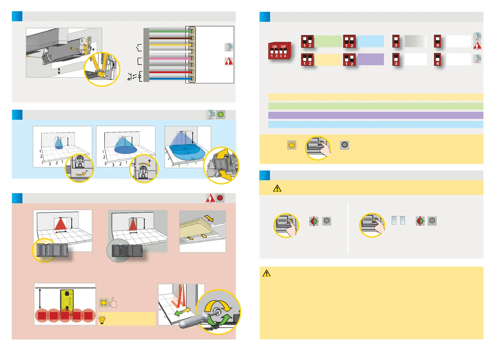
MOUNTING & WIRING
RADAR FIELD - OPENING IMPULSE
FIELD SIZE
ANGLE
GREEN
LED
RED
LED
1
Output status when sensor is operational
2
For compliance with EN 16005, connection
to door controller test output is required.
2.2 m
The door control unit and the door cover profi le must be correctly earthed.
Check position of IR-curtains with
Spotfi nder and adjust if necessary.
ANGLE
Detection fi eld width indicated according to conditions defi ned in EN 16005 and including dimension of test body CA.
Available as accessory
INFRARED FIELD - SAFETY
WIDTH
H W
2.20 m 2.30 m
2.50 m 2.55 m
3.00 m 2.80 m
H W
2.20 m 1.20 m
2.50 m 1.40 m
3.00 m 1.60 m
* in standard presetting
GREEN
BROWN
YELLOW
WHITE
PINK
GREY
RED
2
BLUE
2
POWER SUPPLY
OPENING INPUT
OPENS DOOR
SAFETY INPUT
KEEPS DOOR OPEN
TEST
OUTPUT
RELAY R1
RELAY R2
DOOR
CLOSER
AWAY
SENSOR
The size of the detection fi eld varies according to the mounting height of the sensor.
ORANGE
@ 2.2 m:
Depth of curtain : 8-10 cm
Depth of safety fi eld: 25 cm*
4
5
+
+
- Test the good functioning of the installation before leaving the premises.
- The device cannot be used for purposes other than its intended use. All other uses cannot be guaranteed by the manufacturer
of the sensor.
- The manufacturer of the door system is responsible for carrying out a risk assessment and installing the sensor and the door system
in compliance with applicable national and international regulations and standards on door safety.
- The manufacturer of the sensor cannot be held responsible for incorrect installations or inappropriate adjustments of the sensor.
- Only trained and qualifi ed personnel may install and setup the sensor.
- The warranty is void if unauthorized repairs are made or attempted by unauthorized personnel.
- Avoid touching any electronic and optical components, avoid vibrations, do not cover the sensor and avoid proximity to
neon lamps or moving objects.
- It is recommended to clean the optical parts at least once a year or more often if required due to environmental conditions.
PRESETTINGS
ENVIRONMENT RELAY R1 ACTIVATION
SAFETY INSTRUCTIONS
TIP: Launch an ASSISTED SETUP to verify wiring, position of the
curtains and correct functioning of the sensor.
SETTINGS (by DIP-switch)
QUICK SETUP
ASSISTED SETUP
SETUP
Step outside of the infrared fi eld before launching a setup.
LONG (> 3s)
SHORT
standard
critical
environment
shopping
street
1
hospital
2
standard
extreme
3
1
Can only be used if DIP 4 is OFF.
2
Not available on VIO-DT2. If selected, the presetting «standard» is applicable.
3
Enhanced IR-immunity which excludes EN 16005-conformity of the door system.
4
The opening relay (R1) is activated in case of detection in the radar or infrared fi eld.
motion
or
presence
4
motion
After changing a DIP-switch, the orange LED fl ashes.
A LONG push on the push button confi rms the setting.
Always launch a setup after changes of the DIP-settings.
LONG (> 3s)
critical environment: enhanced immunity (rain, snow, lamps...) and only 1 IR-curtain activated.
shopping street: optimized for narrow sidewalks > the opening relay (R1) is activated in case of detection in radar + IR-fi eld.
hospital: optimized for persons with reduced mobility (PRM)
standard: standard environments (factory setting)
OFF
RED-GREEN
RED-GREEN OFF
OFF
OPEN+CLOSE
ORANGE
 Loading...