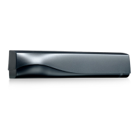
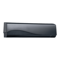
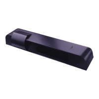
The IXIO-DT1 is a sophisticated motion and presence sensor designed for automatic sliding doors, offering advanced detection capabilities and user-friendly features. It integrates both microwave doppler radar for motion detection and active infrared with background analysis for presence detection, ensuring comprehensive safety and operational efficiency for pedestrian applications.
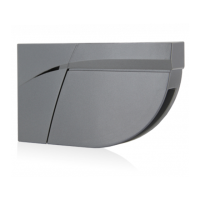
The sensor's design incorporates several key components for optimal performance and ease of use. A protective cover encases the internal electronics, while an LED window provides visual feedback on the device's status. The radar antenna is strategically placed for effective motion sensing, and an AIR curtain width adjustment mechanism allows for precise configuration of the infrared detection field. An LCD screen serves as the primary interface for programming and monitoring, complemented by AIR lenses for the infrared curtains, an AIR curtain angle adjustment knob for fine-tuning the detection area, a main adjustment knob for overall settings, and a main connector for power and communication.
Installation of the IXIO-DT1 requires careful attention to detail to ensure proper functionality and compliance with safety standards. The sensor should be mounted securely, avoiding extreme vibrations, and its bottom edge must be within 2 inches of the bottom of the door header. It is crucial not to cover the sensor, as this can impede its detection capabilities. Additionally, installers should avoid placing moving objects or light sources within the detection field, and highly reflective objects in the infrared field should also be avoided to prevent interference. The harness, which includes power and relay connections, must be routed separately from mains or non-Class 2 voltage cables, or be rated for the mains voltage with appropriate protection. The sensor's power supply must be a Class 2 source limited to 15W.
The IXIO-DT1 offers a range of usage features that enhance its adaptability and performance. The LCD menu provides a clear interface for navigation, allowing users to scroll through options, select settings, and enter passwords for secure access. The display differentiates between factory values and saved values, making it easy to track changes. Users can adjust various parameters, including RADAR field size, shape (wide or narrow), immunity, direction (off, bi-directional, uni-directional, motion-tracking feature, or uni-directional with reentry), hold time, and reentry settings. For the infrared (AIR) component, users can adjust width, immunity, number of curtains, presence time, and frequency. The sensor also supports redirection settings for its relays, allowing for flexible output configurations.
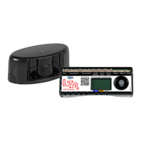
A key feature is the ability to change ZIP codes, which can activate new settings and configurations. The device also supports value checking with a remote control, where pressing a parameter symbol on the remote displays the saved value on the LCD screen, and the green LED blinks to indicate the parameter's setting.
The setup process for the IXIO-DT1 is designed to be straightforward, with both quick (SETUP 1) and assisted (SETUP 2) options. During setup, it is essential to step out of the infrared field to allow the sensor to calibrate correctly. SETUP 1 involves holding the main adjustment knob for 2 seconds or using specific remote control buttons. SETUP 2, an assisted setup, requires a full door cycle test and a reference picture, initiated by holding the knob for 4 seconds or using the remote control. After any installation or setup, it is imperative to test the proper operation of the installation before leaving the premises, with the LED flashing red-green to indicate successful operation.
The infrared safety field can be precisely configured. Users can activate visible spots to verify the position of the AIR curtain, though visibility may vary with external conditions. If spots are not visible, a Spotfinder can be used. The distance between the inner curtain of the inside door sensor and the inner curtain of the outside door sensor should always be less than 8 inches. The AIR curtain angle can be adjusted from -7° to 4° (default 0°) to optimize detection. The width of the detection field can also be masked to reduce its area, with the arrow position determining the width. The size of the detection field varies with mounting height and sensor settings, with a wide setting offering a 1:1 ratio (e.g., a 6-foot mounting height projects a 6-foot detection width at floor level). It is crucial to always verify the actual detection field width by walk-testing according to ANSI 156.10 standards. Additional adjustments for the infrared field are available via the LCD or remote control.
Maintenance of the IXIO-DT1 is minimal but important for sustained performance. It is recommended to clean the optical parts at least once a year, or more frequently if environmental conditions necessitate it. Users should avoid aggressive cleaning products to prevent damage to the optical components.
Safety is paramount with the IXIO-DT1. The door control unit and the header cover profile must be correctly grounded. Only trained and qualified personnel are recommended for the installation and setup of the sensor. Following installation, a thorough test for proper operation, in accordance with ANSI 156.10, must be performed before the premises are left. The warranty is invalidated by unauthorized repairs or repair attempts.
The device provides clear LED signals to indicate its status: green for motion detection, red for presence detection. These LEDs can flash, flash quickly, or remain off, and can also flash red-green or flash a specific number of times to convey different messages.
Troubleshooting guidance is provided through orange LED flashes, each indicating a specific issue. For example, one flash signifies an internal fault, two flashes indicate low/high power supply voltage, four flashes suggest insufficient AIR energy, five flashes point to excessive AIR energy, and eight flashes indicate a faulty AIR power emitter. A continuously illuminated orange LED signals a memory problem. Red LED flashes quickly after an assisted setup if the sensor detects the door, while sporadic red illumination suggests vibration or the sensor seeing the door. Persistent green LED illumination indicates disturbance by rain, leaves, or ghosting from door movement. If the LED and LCD are off, it points to a lack of power. Incorrect output configuration or wiring can lead to the door's reaction not matching the LED signal. Inability to access the LCD menu or change parameters via remote control usually means the sensor is password-protected. If the sensor does not respond to the remote control, the batteries may be dead. Red Visible External Monitoring LED issues (not flashing or continuously flashing) indicate monitoring installation/setup errors, sensor malfunction, or wiring problems. If the door cycles open and remains open, it could be due to incorrect door control settings or improperly set safety/motion outputs.