EasyManua.ls Logo

BEA IXIO-DT1 User Manual

BEA IXIO-DT1
12 pages
To Next Page IconTo Next Page
Page #1 background imageLoading...
Page #1 background image
IXIO-DT1
1
2
9
7
8
5
3
4
6
20.5349
75.5751.12 IXIO-DT1 20230913 Page 1 of 12
MOTION AND PRESENCE SENSOR FOR
AUTOMATIC SLIDING DOORS
ENGLISH
Visit website for
available languages of
this document.
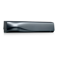
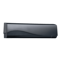
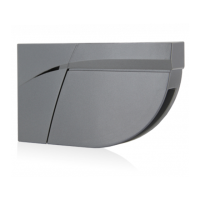
1. cover
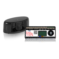
2. LED window
3. radar antenna
4. AIR curtain width adjustment
5. LCD
6. AIR lenses
7. AIR curtain angle adjustment knob
8. main adjustment knob
9. main connector
DESCRIPTION
This device can be expected to comply with Part 15 of the FCC Rules, provided it is assembled in exact accordance with the instructions
provided with this kit. Operation is subject to the following conditions: (1) this device may not cause harmful interference, and (2) this
device must accept any interference received, including interference that may cause undesired operation.
10ICA
Ceiling accessory
10CDA
Curved door accessory
10IMB
Bracket accessory
35.1609: black cover
35.1302: white cover
35.1303: silver cover
10URA
Universal rain accessory
10IXIOSPACER
Spacer
ACCESSORIES
Download the BEA DECODER app
for a quick overview of settings

Other manuals for BEA IXIO-DT1

Questions and Answers:

BEA IXIO-DT1 Specifications

General IconGeneral
TechnologyMicrowave
Mounting HeightUp to 13 ft (4 m)
Current Consumption35 mA (relay energized)
Operating Temperature-4° to +131°F (-20° to +55°C)
Housing MaterialABS
Dimensions4.72 in (H) x 3.15 in (W) x 1.97 in (D) / 120 mm (H) x 80 mm (W) x 50 mm (D)
Tamper SwitchYes
OutputRelay
Humidity0 to 95% non-condensing
Coverage PatternAdjustable
Alarm OutputRelay (NO/NC)
Supply Voltage12 to 24 VAC/VDC
Operating Voltage12 to 24 VAC/VDC

Summary

DESCRIPTION

SAFETY

TECHNICAL SPECIFICATIONS

TECHNOLOGY / PERFORMANCE

Details on detection modes, technology, and performance metrics.

ELECTRICAL

Specifications for output relays, inputs, voltage, power, and noise.

HOW TO USE THE LCD

NAVIGATING IN MENUS

Guide on entering menus, passwords, and language selection.

MOUNTING & WIRING

RADAR OPENING IMPULSE FIELD

INFRARED SAFETY FIELD

SETUP

SETUP 1 (QUICK)

Quick setup procedure using buttons or remote control.

SETUP 2 (ASSISTED)

Assisted setup procedure with full door cycle test.

OVERVIEW OF SETTINGS

LED SIGNALS

TROUBLESHOOTING

E1: ORANGE LED flashes 1x

Internal fault indication and sensor replacement.

E2: ORANGE LED flashes 2x

Low/high power supply voltage and checks.

E4: ORANGE LED flashes 4x

Insufficient AIR energy and adjustment advice.

E5: ORANGE LED flashes 5x

Excessive AIR energy and adjustment advice.

E8: ORANGE LED flashes 8x

AIR power emitter fault and sensor replacement.

The LED and the LCD displays are off

No power to sensor or wiring issues.

RED Visible External Monitoring (Test Indication LED) does not flash

Monitoring installation/setup error or TEST mode not active.

Related product manuals