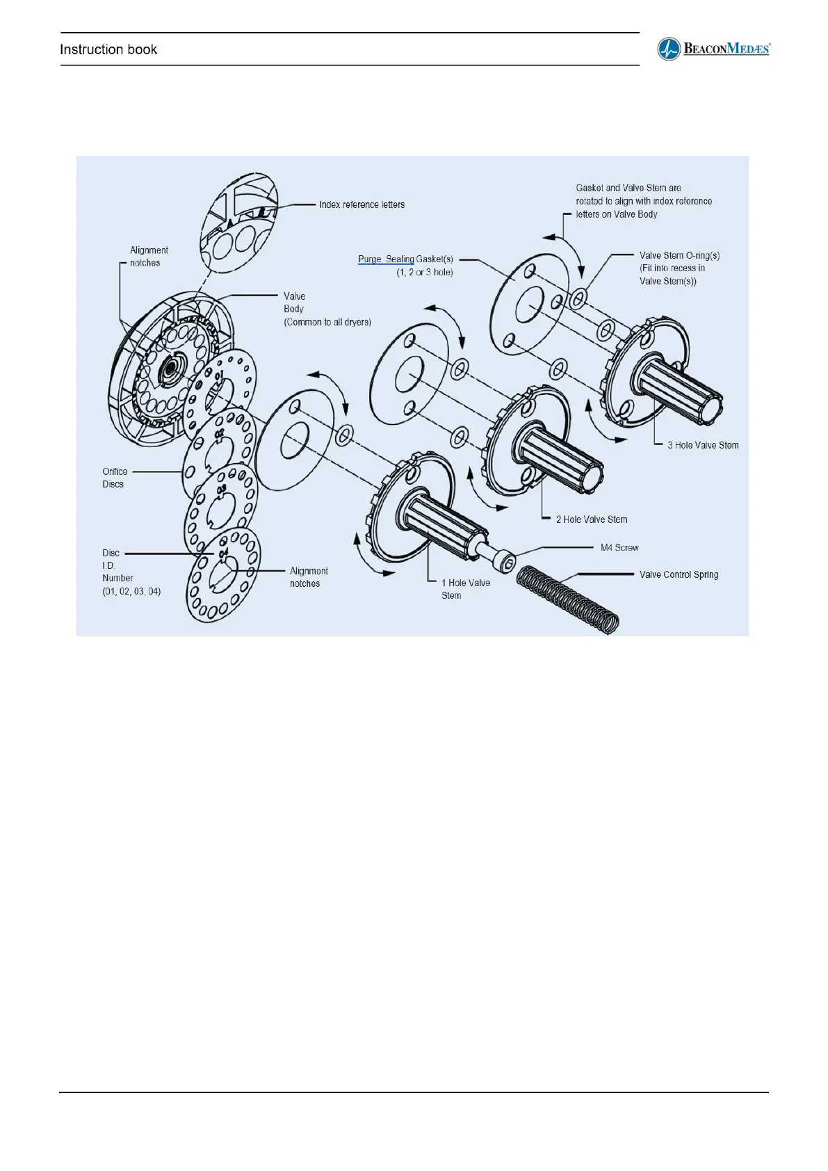
• Reference figure above and the Purge Plug Identification Table on page 78.
• Once the correct purge body (1, 2 or 3 hole) and orifice disc (01, 02, 03 or 04) has been selected
per the instructions on Page 78, the purge valve may be assembled.
• The index letters located on the purge valve body correspond with the selected orifice sizes per
the Table on Page 78.
• Place the appropriate orifice disc onto the valve body, taking care to align the notches. The disc
will only fit in one position. Place the valve stem O-ring(s) into their corresponding recesses on
the back of the valve stem.
• Align the holes in the purge sealing gasket with the corresponding holes in the valve stem.
• Rotate the valve stem assembly so that the correct orifice letters align with the notches
corresponding to the holes (1, 2 or 3) in the valve stem.
• Press the assembly together and fasten with the M4 screw.
• Double check to make sure that the open orifice holes correspond with the correct orifice
selection as identified earlier.