8.7 Purge orifice identification/changeout dMED 45 - 300
• Reference figure page 79 and the Purge Plug Identification Table.
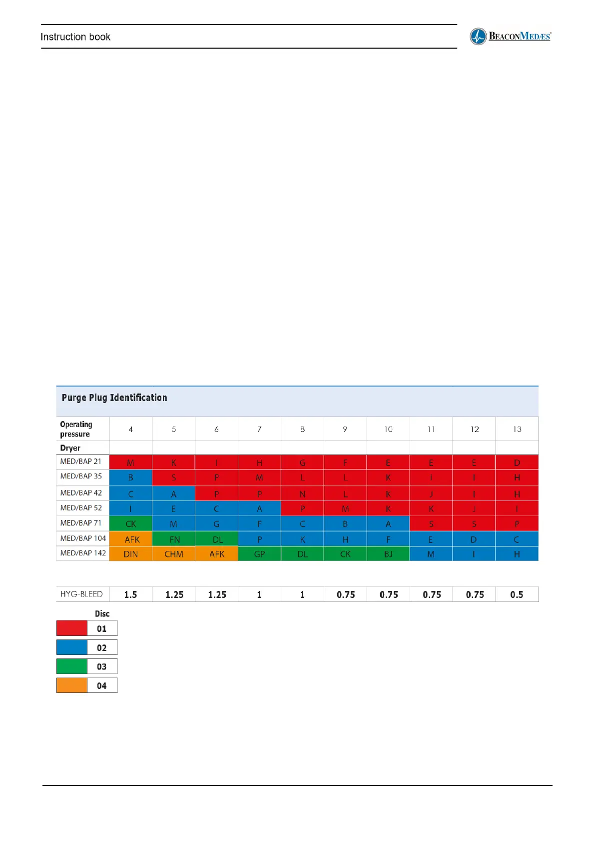
• The lettering (A through S), located on the purge valve body, indicates the orifice size selected to
suit the operating pressure of the dryer per the chart below.
• If the inlet pressure to the dryer will be different than the pre-set orifice size, the purge valve can
be adjusted.
• Most dryers use a single orifice purge valve represented by the Blue and Green single letter
references in the table below.
• Larger dryers may require a two or three hole purge valve as represented by the Red and Yellow
two and three letter references.
• To select the correct orifice size, locate the appropriate dryer model at the left side of the table and
then the operating pressure at the top.
• Make sure that the correct valve body (1, 2 or 3 hole) and orifice disc (01, 02, 03 or 04) has been
supplied with the dryer. The discs have the number (01, 02, 03 or 04) stamped out at the top.