SC01/SC02/SC11/SC12
Sc12hw09.doc page 7 of 37 24.11.1999 V0.9
TF/WB
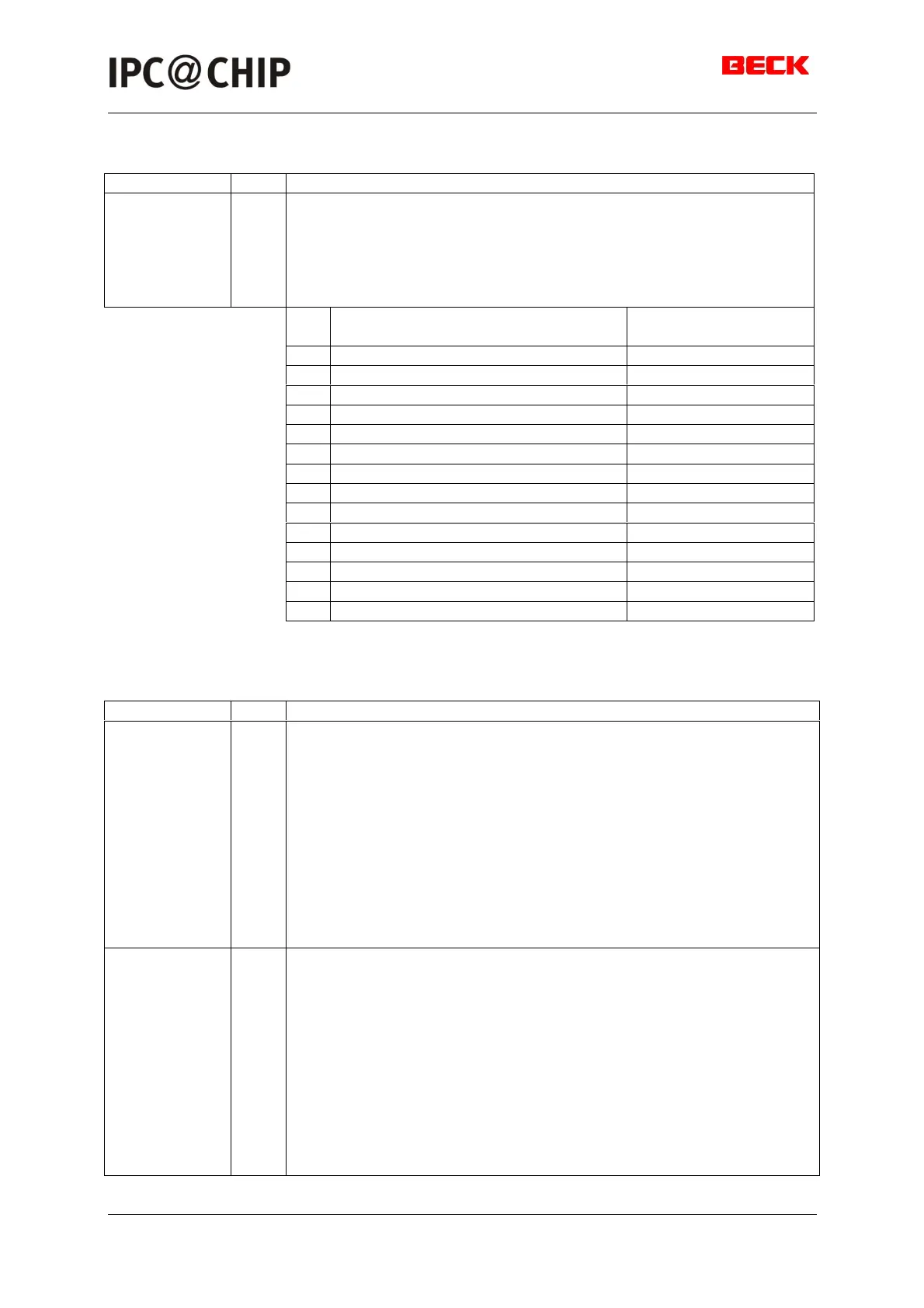
4.2 Programmable I/O Pins
Pin Name Type Function
PIO[0..13] I/O Programmable I/O Pins (input/output, asynchronous,
open-drain)
The IPC@CHIP family microcontroller provides 14 individually
programmable I/O pins. Each PIO can be programmed with the
following attributes: PIO function (enabled/disabled), direction
(input/output), and weak pullup or pulldown.
PIO
##
After power-on reset, the PIO
pin defaults to
programmable as
Input with
0 Input without pullup
1 Input without pullup
2 PCS6# pullup
3 Input with pullup pullup / pulldown
4 Input with pullup pullup
5 Output high pullup
6 Input with pullup pullup
7 RxD0 pullup
8 TxD0 pullup
9 Input with pullup pullup
10 Output high pullup
11 TxD1 pullup
12 RxD1 pullup
13 Output low pulldown
4.3 Programmable Chip Selects
Pin Name Type Function
PCS[0..3] O Peripheral Chip Selects (output, synchronous)
These pins indicate to the system that an I/O memory access is in
progress to the corresponding region of the peripheral memory.
PCS3–PCS0 are three-stated and held resistively High during a
bus hold condition. In addition, PCS3–PCS0 each have a weak
internal pullup resistor that is active during reset. The PCS
outputs assert with the multiplexed AD address bus. Note also
that each peripheral chip select asserts over a 256-byte address
range, which is twice the address range covered by peripheral
chip selects in the 80C186 and 80C188 microcontrollers. PCS3–
PCS0 also have extended wait state options, default is 15 wait
states.
PCS[5..6] O Peripheral Chip Selects (output, synchronous)
These pins indicate to the system that an I/O memory access is in
progress to the corresponding region of the peripheral memory.
PCS6–PCS5 are three-stated and held resistively High during a
bus hold condition. In addition, PCS6–PCS5 each have a weak
internal pullup resistor that is active during reset. The PCS
outputs assert with the multiplexed AD address bus. Note also
that each peripheral chip select asserts over a 256-byte address
range, which is twice the address range covered by peripheral
chip selects in the 80C186 and 80C188 microcontrollers. PCS6–
PCS6 also have extended wait state options, default is 3 wait
states, on SC02 and SC12 changing is not allowed.