14 | VT 4.10, VT 4.16, VT 4.25, VT 4.40, VX 4.10, VX 4.16, VX 4.25, VX 4.40
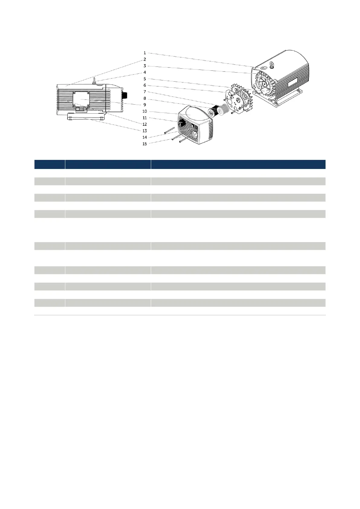
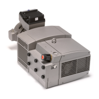
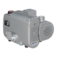
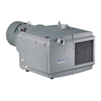
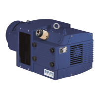
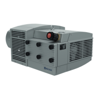
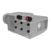
4.4 COMPONENT ILLUSTRATION
VT 4.10, VT 4.16, VT 4.25, VT 4.40, VX 4.10, VX 4.16, VX 4.25, VX 4.40
Connection of the vacuum line
Flow optimisation, noise reduction
The pump unit includes pump housing, piston and slide valve
Forms the compression chambers
Lateral closure of the pump casing
Optionally, a further filter cartridge can be installed, which
additionally filters the carbon abrasion of the sliders from the
exhaust air.
Filtering of the evacuated intake air (exception VX 4.25/0-47).
Terminal box with motor type
plate
Electrical connection Conformity mark and technical data - Motor
Flow optimisation, noise reduction
Setting the required vacuum
Stable installation and fastening of the pump
Marking of conformity and technical data - Pump
Evacuated air outlet, vacuum safety device
Table 4.4: Component illustration 1