Product overview
BC9000 and BC910010 Version: 4.0.0
outputs return in the inactive state. The timeout periods for the Bus Couplers correspond to the usual
settings for the fieldbus system. When converting to a different bus system it is necessary to bear in mind the
need to change the timeout periods if the bus cycle time is longer.
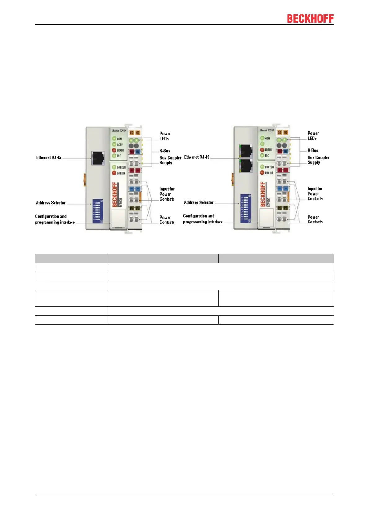
The interfaces
A Bus Coupler has six different methods of connection. These interfaces are designed as plug connectors
and as spring-loaded terminals.
2.3 Technical data
Fig.2: BC9000 and BC9100
System data Ethernet (BC9000) Ethernet (BC9100)
Number of I/O modules only limited by the IP address space
Number of I/O points depending on controller
Data transfer medium 4 x 2 twisted-pair copper cables; category 3 (10 Mbit/s), category 5 (100Mbit/s)
Distance between
modules
100 m (distributor hub to BC9000) Line: max. 100m between two BC9100
Data transfer rate 10 / 100 Mbit/s
Topology star wiring star wiring, up to 20 BC9100 in one line