Programming
BC9000 and BC9100 37Version: 4.0.0
Fig.24: Task Time
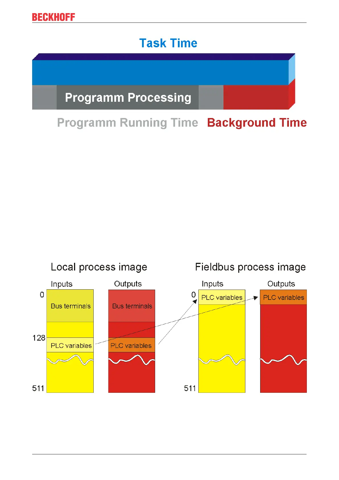
6.3 PLC Variables
The PLC variables act as the interface between the local process image of the bus controller and the
fieldbus process image for a higher-level controller. This will first be explained on the basis of the default
setting.
Bus Terminals in the BC's local process image
All the connected Bus Terminals are assigned to the local process image. The PLC variables are located
from address 128 onwards. You can change both this starting address and the length of these data (default
16bytes).
Data that is to be read by a higher level controller is written into the output process image. This is input data
for the higher level controller. Data that is to be transferred from the higher level controller to the BC is output
data for the controller and input data for the BC. The following diagram may clarify this.
Fig.25: Bus Terminals in the BC's local process image
Assign bus terminals to the higher level controller
You can also assign the Bus Terminals directly to the higher level controller. The general scheme of the
fieldbus process image is such that the analog Bus Terminals are mapped into this process image first. The
digital Bus Terminals then follow, while the PLC variables come last.