Fieldbus system
BC9000 and BC910066 Version: 4.0.0
Watchdog
The watchdog is active under the factory settings. After the first write telegram the watchdog timer is initiated,
and is triggered each time a telegram is received from this device. Other devices have no effect on the
watchdog. A second approach, which represents a more sensitive condition for the watchdog, is for the
watchdog only to be re-triggered after each write telegram. To do this, write a zero into register 0x1122
(default value "1").
The watchdog can be deactivated by writing a zero to offset 0x1120. The watchdog register can only be
written if the watchdog is not active. The data in this register is retained.
Watchdog register
If the watchdog timer on your slave has elapsed it can be reset by writing twice to register 0x1121. The
following must be written to the register: 0xBECF 0xAFFE. This can be done either with function 6 or with
function 16.
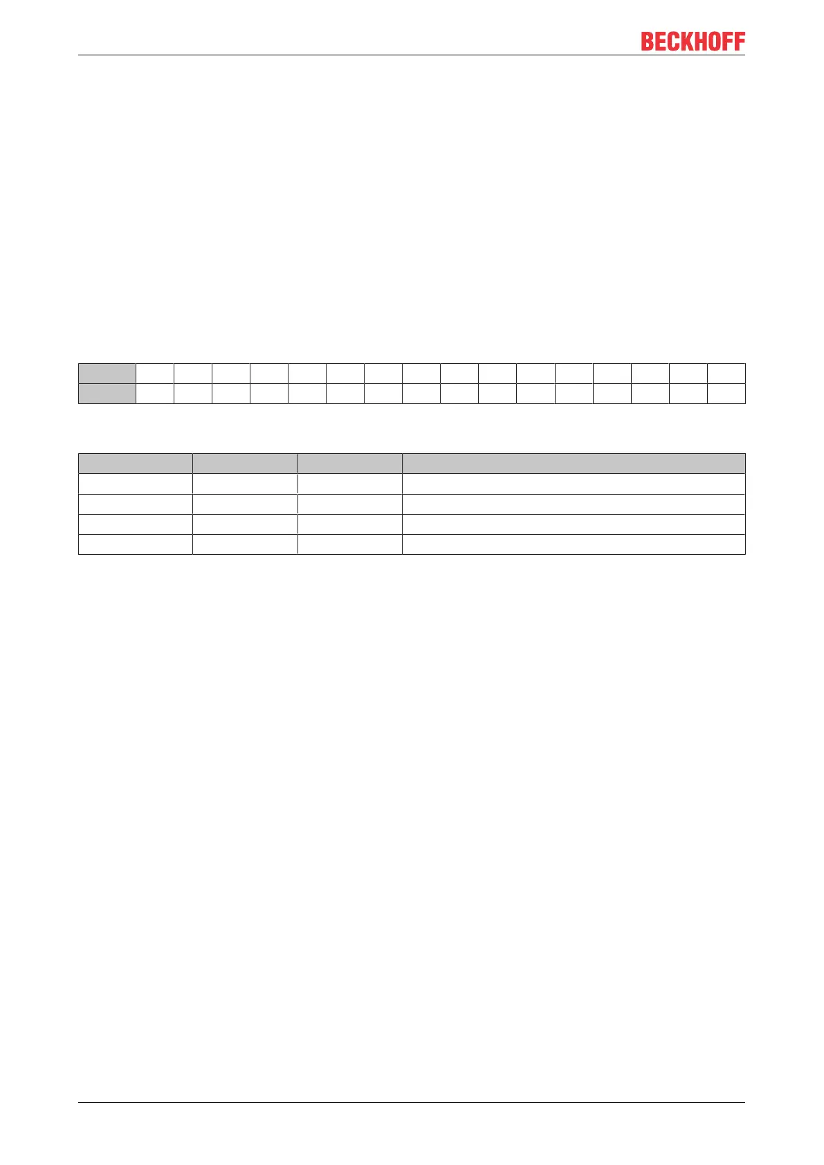
The Bus Coupler's status register
Bit 15 14 13 12 11 10 9 8 7 6 5 4 3 2 1 0
Name FB - - - - - - - - - - - - - CNF KB
Legend
Bit Name Value Description
15 FB 1
bin
Fieldbus error, watchdog time elapsed
14...2 - - reserved
1 CNF 1
bin
Bus Coupler configuration error
0 KB 1
bin
Bus Terminal error
ModbusTCP mode
The fast Modbus mode should only be used in small local networks. The fast ModbusTCP is not active under
the default settings. If problems are found to occur with this type of communication, the Bus Coupler should
be switched to "normal" ModbusTCP communication. The mode is set in the Modbus interface, offset
0x1123. It is necessary to reset the coupler (e.g. using ModbusTCP function 8) after the change. It is not
permitted to send more than one Modbus service within one Ethernet frame in fast Modbus mode.
2 byte PLC interface
Registers in the complex terminals and Bus Terminal Controller registers can be both read and written using
the 2 byte PLC interface. The complex terminal registers are described in the associated terminal
documentation. The Bus Coupler registers can be used, for example, to read terminal bus diagnostics data,
the terminal composition or the cycle times, and the programmed configuration can be written. It is also
possible for a manual K-bus reset to be carried out. The 2-byte PLC interface requires two bytes each of
input and output data. They are handled using a special protocol. A description of the 2 byte PLC interface,
the registers available in the Bus Couplers and of function blocks for various PLC systems that support the 2
byte PLC interface can be supplied on request.
2 byte diagnostic interface
The terminals' error messages can be sent over the 2-byte diagnostic interface. K-bus diagnostics must
however be activated for this purpose. The 2-byte diagnostic interface occupies two bytes each of input and
output data. A special protocol is processed via these two bytes. A description of the 2 byte-diagnostic
interface can be supplied on request.