Mounting and wiring
BK11x0, BK125040 Version: 4.1
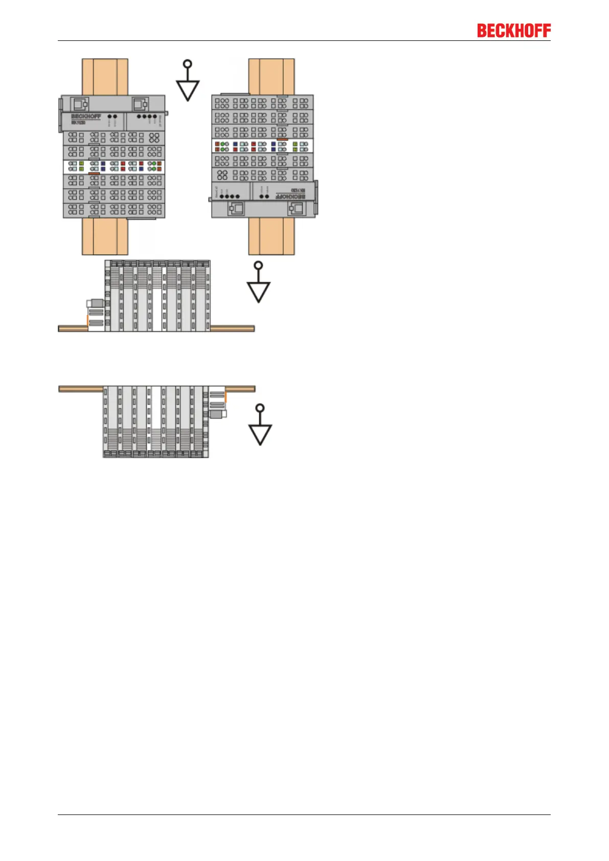
Fig.29: Other installation positions
5.5 Power supply, potential groups
Bus Coupler power supply
The Bus Couplers require a 24 V DC supply for their operation. The connection is made by means of the
upper spring-loaded terminals labelled 24V and 0V. The supply voltage is used by the Bus Coupler
electronics and for direct voltage generation for the E-bus. The voltage generation for the E-bus takes place
in a DC/DC converter without electrical isolation.
The EK1xxx units supply the E-bus with max. 2,000 mA E-bus current. Power feed terminals are to be
inserted if the added terminals require more current.
Input for power contacts
The bottom six connections with spring-loaded terminals can be used to feed the supply for the peripherals.
The spring-loaded terminals are joined in pairs to a power contact. The feed for the power contacts has no
connection to the voltage supply for the Bus Coupler. The design of the feed permits voltages of up to 24V.
The assignment in pairs and the electrical connection between feed terminal contacts allows the connection
wires to be looped through to various terminal points. The current load via the power contacts may not
permanently exceed 10 A; the supply line must therefore be protected by a 10 A fuse (slow-blow).
 Loading...