Parameterization and commissioning
BK11x0, BK1250 75Version: 4.1
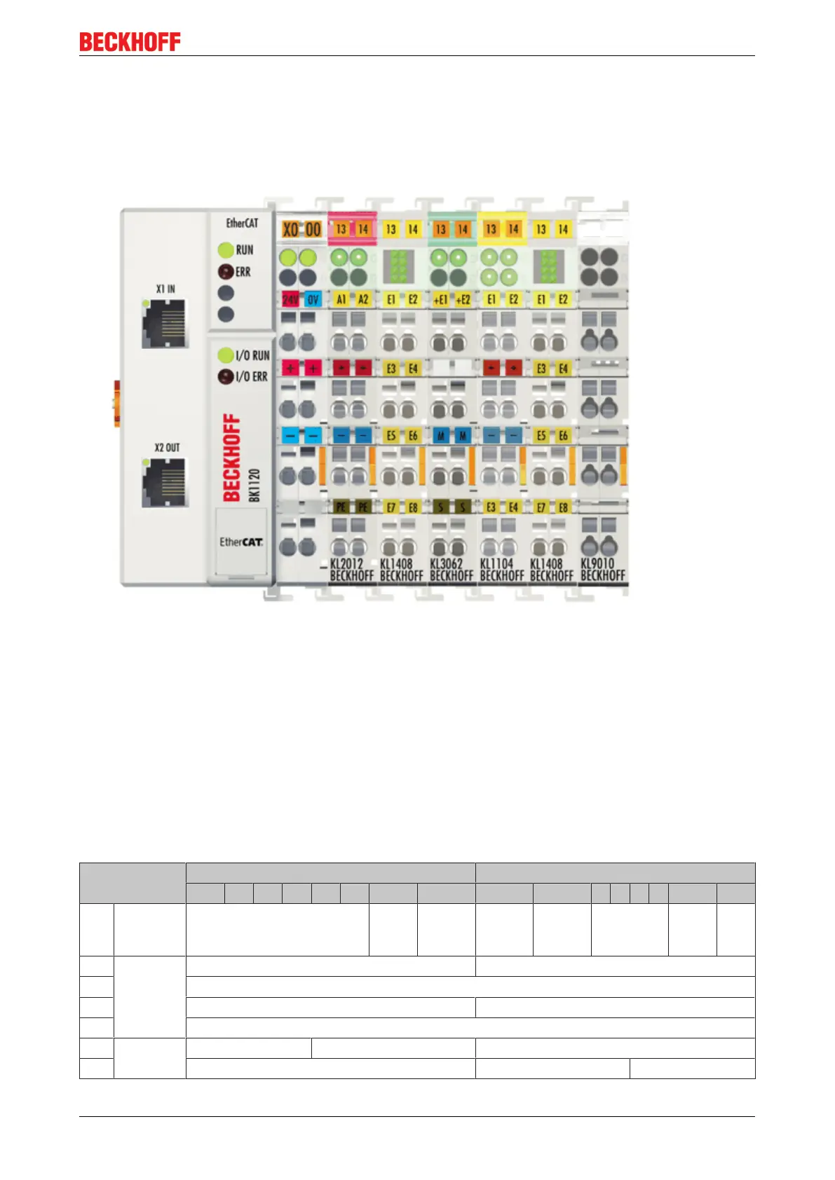
6.4.11 Process image example
The following examples with the BK1120 illustrates the process image of a Bus Terminal block.
Fig.52: Configuration example for explaining the process image
The Bus Terminal block shown in the example consists of a Bus Coupler with attached KL2012, KL1408,
KL3062, KL1104, KL1408 and KL9010 (see image). For complex mapping with Word alignment (factory
settings) all non-digital terminals are shown in the process input and output image. Please refer to the
relevant terminal documentation regarding the mapping details. The non-digital terminals are mapped first,
followed by the digital terminals. The first 16 bits of the process image are reserved for the status word
(process input image) and the control word (process output image).
Process input image
The status word (SW) is located in the output process image, and is transmitted from terminal to the
controller.
Word-Offset High byte Low byte
15 14 13 12 11 10 9 8 7 6 5 4 3 2 1 0
0 Status K-bus
overr.
Outputs
disabled
no valid
output
data
no valid
input
data
Config
.
Error
K-
bus
Error
1 KL3062
(non-
digital)
Dummy for Word alignment Status byte channel 1
2 Process data channel 1
3 Dummy for Word alignment Status byte channel 2
4 Process data channel 2
5 Digital
terminals
KL1408 (2) KL1104 KL1408 (1)
6 KL1408 (2)
 Loading...