Eiserstraße 5 / D-33415 Verl / Telefon 05246/963-0 / Telefax 05246/963-149
BK5200 Basic information 10
BK5200
The peripheral data in the process image
When the bus coupler is first switched on it determines the configuration of
the attached input/output terminals and automatically assigns the physical
slots of the input/output channels to the addresses in the process image.
The bus coupler sets up an internal list of assignments in which each of the
input and output channels has a specific position in the process image. A
distinction is made here between input and output and between bit-oriented
(digital) and byte-oriented (analog, or complex) signal processing.
It also forms two groups, whereby one contains only inputs and the other
only outputs. In each group, the byte-oriented channels take the lowest
addresses, in ascending order, and these are then followed by the bit-
oriented channels.
Digital signals
(bit-oriented)
Digital signals are bit-oriented. This means that one bit of the process
image is assigned to each digital channel. The bus coupler sets up a block
of memory containing the current input bits and arranges to immediately
write out the bits from a second block of memory which belongs to the out-
put channels.
The precise assignment of the input and output channels to the process
image of the control unit is explained in detail in the Appendix by means of
an example.
Analog signals
(byte-oriented)
The processing of analog signals is always byte-oriented and analog input
and output values are stored in memory in a two-byte representation. The
values are held as ”SIGNED INTEGER” or ”twos-complement”. The digit
”0” represents the input/output value ”0V”, ”0mA” or ”4mA”. When you use
the default settings, the maximum value of the input/output value is given
by ”7FFF” hex. Negative input/output values, such as -10V, are represen-
ted as ”1000” hex and intermediate values are correspondingly proportional
to one another. The full range of 15-bit resolution is not realized at every
input/output level. If you have an actual resolution of 12 bits, the remaining
three bits have no effect on output and are read as ”0” on input. Each
channel also possesses a control and status byte in the highest value byte,
although version 2.0 of the DeveNet coupler does not permit the control
and status byte to be read. An analog channel is represented by 2 bytes in
the process image.
Special signals and
interface
A bus coupler supports bus terminals with additional interfaces, such as
RS232, RS485, incremental encoder, etc.. These signals can be regarded
in the same way as the analog signals described above. A 16-bit data
width may not be sufficient for all such special signals; the bus coupler can
support any data width.
Default assignment of
inputs and outputs to the
process image
When the bus coupler is first switched on it determines the number of atta-
ched bus terminals and sets up a list of assignments. This list distinguishes
between analog channels and digital channels and between input and out-
put; which are grouped separately. The assignments begin immediately to
the left of the bus coupler. The software in the bus coupler creates the
assignment list by collecting the entries for the individual channels one at a
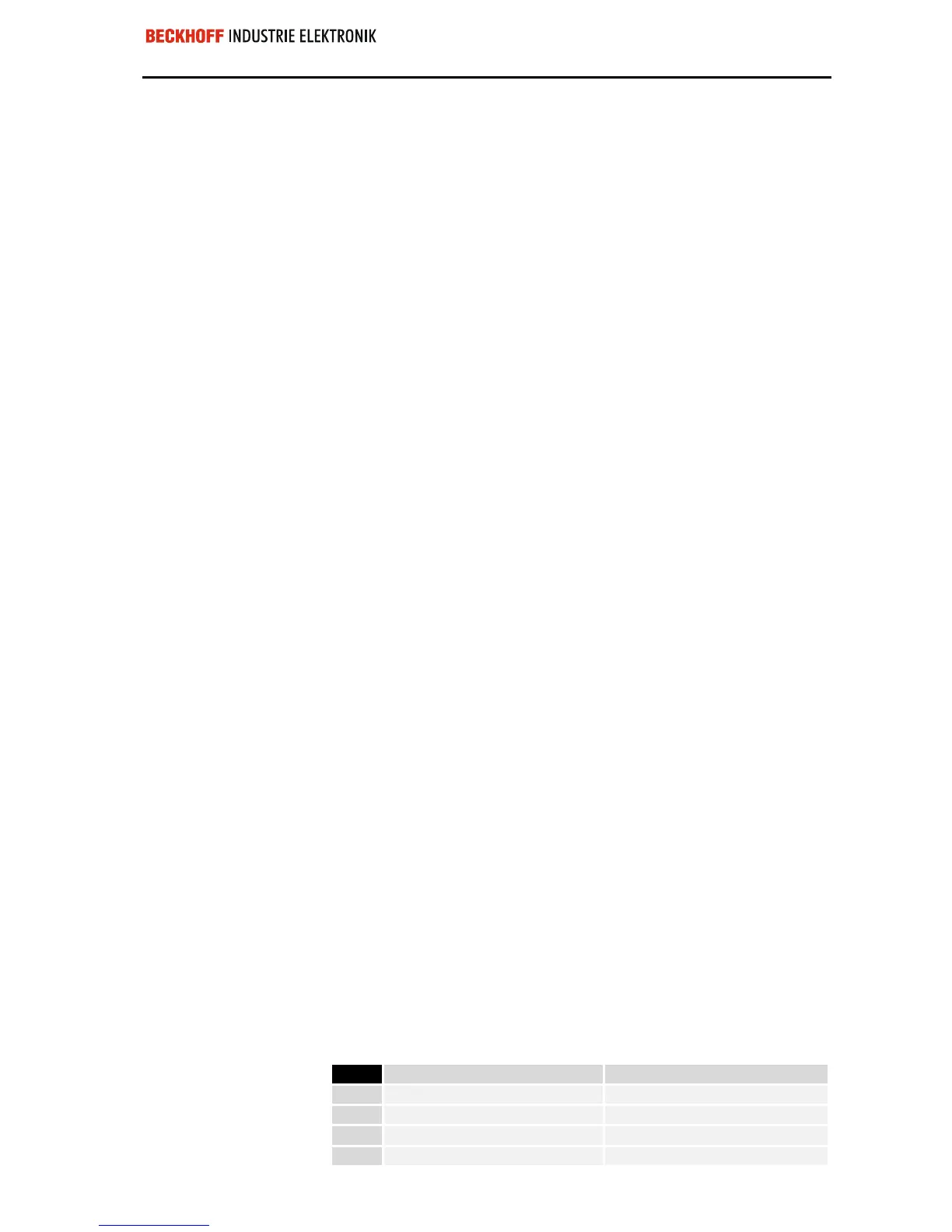
time, counting from left to right. These assignments distinguish four groups:
Function type of the channel Assignment level
1.
Analog outputs byte-wise assignment
2.
Digital outputs bit-wise assignment
3.
Analog inputs byte-wise assignment
4
Digital inputs bit-wise assignment
 Loading...
