Eiserstraße 5 / D-33415 Verl / Telefon 05246/963-0 / Telefax 05246/963-149
7 BK5200 Basic information
BK5200
The operating modes of the bus coupler
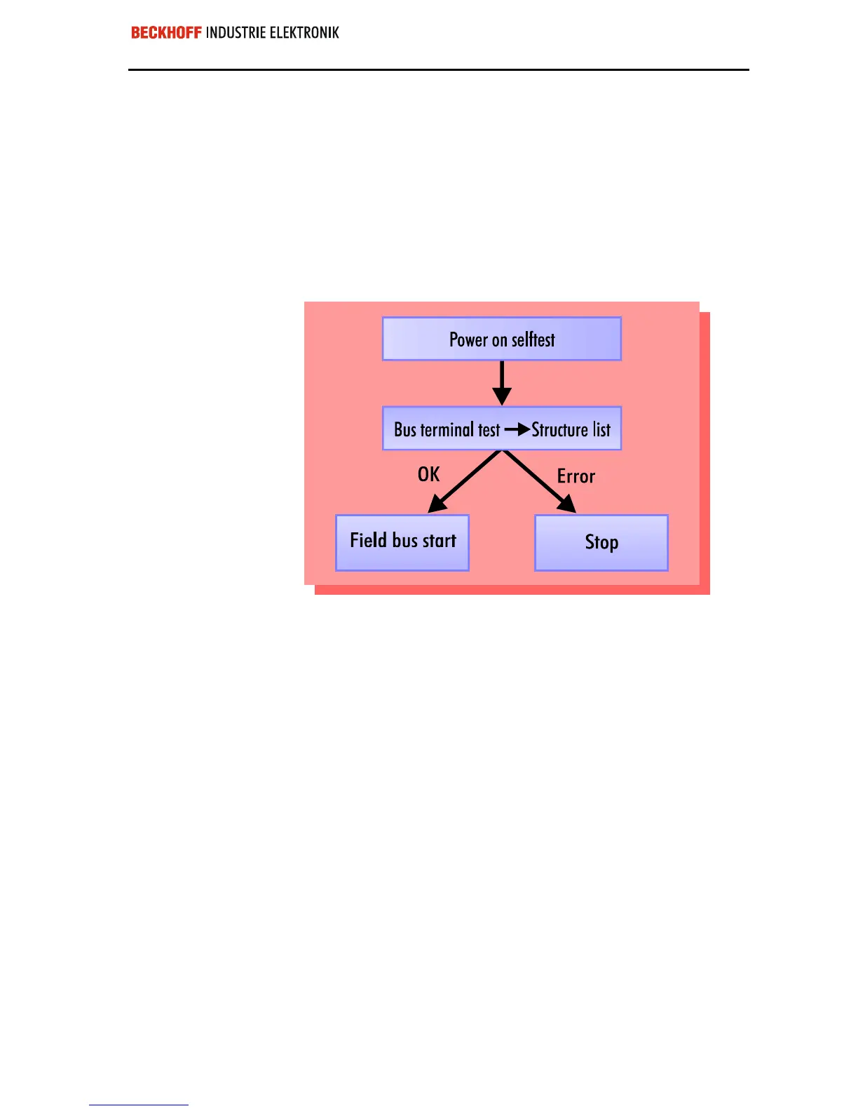
When it is first switched on the bus coupler carries out a self-test to check
the functions of its components and the communications of the K-bus, and
while this is going on the red I/O LED will flash. When the self-test has
been completed successfully, the bus coupler will begin to test the atta-
ched bus terminals (the ”bus terminal test”) and read in the configuration
from which it constructs an internal structure list, which is not accessible
from outside. If an error occurs the bus coupler will enter the operating
mode ”STOP”. If the start-up sequence is completed without errors the bus
coupler will enter the mode ”fieldbus start”.
Start-up behavior of the bus
coupler
The bus coupler reports the error to the master by means of the DeviceNet
diagnostics. Clearing the error returns the bus coupler to its normal opera-
ting mode.
 Loading...
