Eiserstraße 5 / D-33415 Verl / Telefon 05246/963-0 / Telefax 05246/963-149
17 BK5200 BK52x0 DeviceNet
BK5200
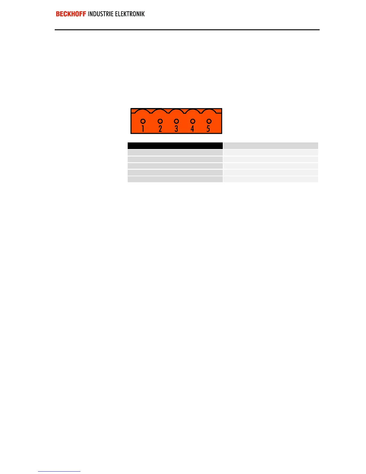
Pin-out
DeviceNet connection
The bus and the terminals
have separate power supp-
lies. Both power supplies
must be connected
A 5-pin plug is supplied for connecting the DeviceNet bus cable. When it is
plugged into the bus coupler, pin 1 is at the top. The illustration shows the
socket which is located on the bus coupler. The power supply delivered by
this plug is isolated from the power supply of the terminal to the right of the
bus coupler. Both power sources must be connected before the system
can operate.
Pin-out of DeviceNet connection
1
V+
2
CAN-H
3
Drain
4
CAN-L
5
V-
Exchanging data
Data string from the
DeviceNet master to the
bus coupler:
first byte-oriented data,
and then bit-oriented data.
4 bytes for 2-channel
analog output terminals
2 bits for 2-channel digital
output terminals
First the data from all the
analog outputs
then the data for the digital
outputs,
in each case, transferred as
bytes
Data is transferred between masters and slaves in the form of objects. The
bus coupler recognizes two objects: an input object and an output object.
You can use the Software Manager to map the input/output bytes onto
specific memory areas in the control unit. The bus coupler uses a consi-
stent algorithm to correlate the object data to the peripherals. Various ex-
amples of correlations between addresses and peripherals are explained in
the appendix. A (data) object which is transferred from the DeviceNet ma-
ster to the bus coupler must begin with the byte-oriented values, this is the
data for the analog output terminals. The bit-oriented data for digital out-
puts may not be transmitted until all the byte-oriented values have been
sent.
Analog outputs receive 16 bits of data, i.e. two bytes, for each channel. An
analog output terminal with 2 channels must therefore receive 4 bytes. A
digital output terminal with 2 channels needs a total of 2 bits of data, one
for each channel.
The first 4 bytes of an object which is transferred to the terminal row are
assigned to the first analog output terminal, this is the analog output termi-
nal nearest to the bus coupler. Other terminals which are located between
the bus coupler and the first analog output terminals are disregarded.
The next four bytes of the object go to the second analog output terminal in
the terminal row. Any other terminals between the first and second analog
output terminals are disregarded.
When the last analog output terminal in the terminal row has received its
data, the digital outputs are served. Data is always transferred in the form
of bytes, so the next byte from the data string contains data for 8 digital
outputs. Bit 0 and bit 1 are assigned to channels 1 and 2 of the first digital
output terminal after the bus coupler. Other types of terminal which are
located in between are ignored.
Bits 2 and 3 go to the 2 channels of the second digital output terminal, bits
4 and 5 to the third and bits 6 and 7 to the fourth. There may be other ter-
minals located between these digital output terminals, if so they will be
disregarded.
 Loading...
