Eiserstraße 5 / D-33415 Verl / Telefon 05246/963-0 / Telefax 05246/963-149
Appendix 22
BK5200
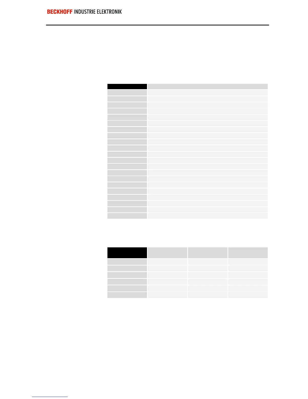
Sample arrangement of a process image in
the bus coupler
The following example will illustrate the assignment of input/output chan-
nels to the process image. Our sample construction is to consist of the
following bus terminal components:
For this configuration
Position Function component on the track
the bus coupler will create
POS01
Bus coupler
the list of assignments
POS02
2-channel digital input
shown below
POS03
2-channel digital input
POS04
2-channel digital input
POS05
2-channel digital input
POS06
2-channel digital input
POS07
2-channel digital output
POS08
2-channel digital output
POS09
2-channel digital output
POS10
2-channel analog input
POS11
2-channel analog output
POS12
2-channel analog output
POS13
2-channel analog input
POS14
Power input terminal
POS15
2-channel digital input
POS16
2-channel digital input
POS17
2-channel digital input
POS18
2-channel digital output
POS19
2-channel digital output
POS20
2-channel analog output
POS21
End terminal
By default all analog terminals are mapped without a Control/Status byte.
Please read the technical documentation for the analog terminals for
further details.
Area for byte-oriented
data, analog outputs
Relative byte
address
Bit position Process image in
the control unit
Position in the
block
0, 1
none O0, O1 POS11
2, 3
none O2, O3 POS11
4, 5
none O4, O5 POS12
6, 7,
none O6, O7 POS12
8, 9
none O8, O9 POS19
10, 11
none O10, O11 POS19
 Loading...
