Eiserstraße 5 / D-33415 Verl / Telefon 05246/963-0 / Telefax 05246/963-149
23 Appendix
BK5200
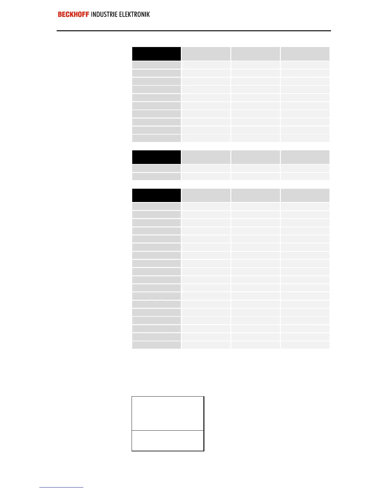
Area for bit-oriented data,
digital outputs
Relative byte
address
Bit position Process image in
the control unit
Position in the
block
12
0 O12 POS07
12
1 O12 POS07
12
2 O12 POS08
12
3 O12 POS08
12
4 O12 POS09
12
5 O12 POS09
12
6 O12 POS18
12
7 O12 POS18
13
0 O13 POS19
13
1 O13 POS19
Area for byte-oriented
data, analog inputs
Relative byte
address
Bit position Process image in
the control unit
Position in the
block
0, 1
none I0, I1 POS10
2, 3
none I2, I3 POS13
Area for bit-oriented data,
digital inputs
Relative byte
address
Bit position Process image in
the control unit
Position in the
block
4
0 I4 POS01
4
1 I4 POS01
4
2 I4 POS02
4
3 I4 POS02
4
4 I4 POS03
4
5 I4 POS03
4
6 I4 POS04
4
7 I4 POS04
5
0 I5 POS05
5
1 I5 POS05
5
2 I5 POS06
5
3 I5 POS06
5
4 I5 POS15
5
5 I5 POS15
5
6 I5 POS16
5
7 I5 POS16
6
0 I6 POS17
6
1 I6 POS17
The items POS14 and POS21 are not relevant to data exchange and do
not appear in the list. If a byte is not fully used, for example I8, the bus
coupler pads its remaining bits with zeroes.
Overview of the distribution of the process image in the bus coupler:
Output data
in the bus coupler
O0
...
byte-oriented data
...
O11
O12
bit-oriented data
O13
 Loading...
