Eiserstraße 5 / D-33415 Verl / Telefon 05246/963-0 / Telefax 05246/963-149
5 BK5200 Basic information
BK5200
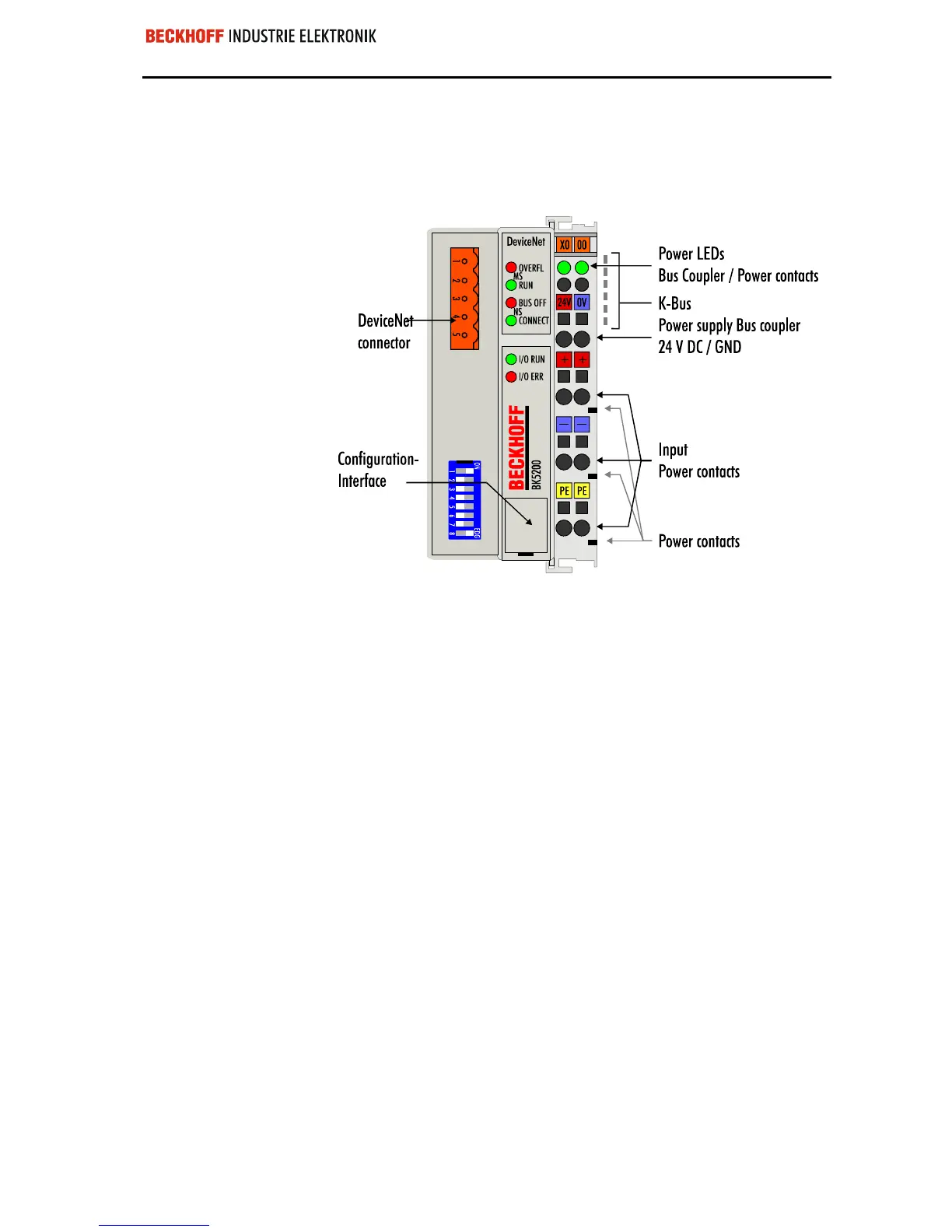
The interfaces
There are six ways of making a connection to a bus coupler. These interfa-
ces are designed as plug connections and spring terminals.
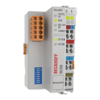
The DeviceNet coupler
BK5200
Power supply
24 V DC on the topmost
terminals ”24 V” and ”0 V”
The bus couplers need an operating power of 24 V DC which is connected
via the topmost spring terminals, labeled ”24 V” and ”0 V”. This power
supply serves not only the electronic components of the bus coupler but
(via the K-bus) also the bus terminals. The power supply of the bus coupler
circuitry and that of the K-bus are electrically isolated from the voltage of
the field level.
Power supply to the power contacts
Lower 3 terminal pairs for
power input
maximum 24 V
maximum 10 A
The six lower connections with spring terminals can be used to supply po-
wer to the peripherals. The spring terminals are connected in pairs to the
power contacts. The power supply to the power contacts has no connec-
tion to the power supply of the bus couplers. The power input is designed
to permit voltages up to 24 V. The pair-wise arrangement and the electrical
connection between the feed terminal contacts makes it possible to loop
through the wires connecting to different terminal points. The load on the
power contact may not continuously exceed 10 A. The current capacity
between two spring terminals is the same as the capacity of the connecting
wires.
Power contacts
Spring contacts at the side
On the right-hand side face of the bus coupler are three spring contacts
which are the power connections. The spring contacts are recessed in slots
to prevent them from being touched. When a bus terminal is connected,
the blade contacts on the left-hand side of the bus terminal are connected
to the spring contacts. The slot and key guides at the top and bottom of the
bus couplers and bus terminals ensure reliable location of the power con-
tacts.
 Loading...
