Eiserstraße 5 / D-33415 Verl / Telefon 05246/963-0 / Telefax 05246/963-149
BK5200 Basic information 4
BK5200
Power input terminals
for separately powered
groups
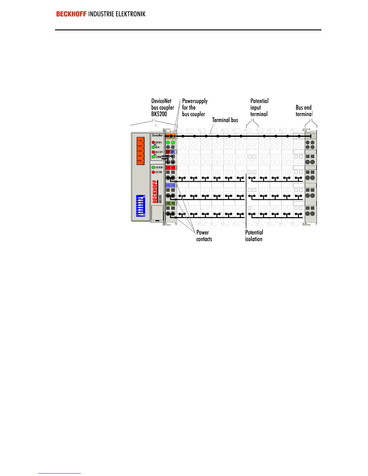
Three power contacts pass the operating power to the following terminals.
You can use power input terminals to subdivide the terminal row as desired
into groups, each with a separate power supply. These power input termi-
nals are not taken into account for addressing the terminals, you can insert
them at any position along the terminal row.
You can install up to 64 terminals on a terminal row, including power input
terminals and the end terminal.
The principle of the bus
terminal
Bus couplers for various
fieldbus systems
You can use a variety of bus couplers to attach the electronic terminal row
quickly and easily to the various fieldbus systems, and you can also sub-
sequently convert to a different fieldbus system. The bus coupler deals with
all the necessary monitoring and control tasks for operating the attached
bus terminals, indeed all the operation and configuration of the bus termi-
nals is carried out via the bus coupler. The fieldbus, K-bus and I/O level are
electrically isolated.
If the exchange of data across the fieldbus is temporarily interrupted, logic
states are preserved, digital outputs are cleared and analog outputs revert
to a reset value which can be individually configured for each output when
the equipment is set up.
 Loading...
