Eiserstraße 5 / D-33415 Verl / Telefon 05246/963-0 / Telefax 05246/963-149
15 BK5200 BK52x0 DeviceNet
BK5200
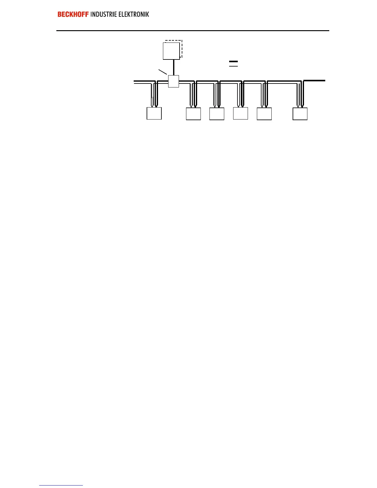
Node
Node Node
Node
Node Node
Power Tap
Signal Conductor
Power Conductor
24 Volt
Power
Supply
The bus cable may consist of a main line with branch lines up to 12m long.
It is important that both ends of the main line should carry 121Ω termina-
ting resistors. You can operate up to 64 subscribers on one line. If you
want to be able to plug and unplug bus couplers while the equipment is in
operation you should attach the terminating resistors firmly to the bus
cable.
Using the Software
Manager to set up the
system parameters.
It is advisable to use a special software program to set up the system para-
meters, for example Allen Bradley’s ”Software Manager” which enables
you to record the parameter data in the master. When it is first switched on,
the master will compare its stored settings with the actual configurations of
each of the stations. The exchange of user data between master and slave
will not be set up unless all the parameters agree. Setting the parameters
for the master is carried out directly via the DeviceNet connection. The
DeviceNet system does not use a separate interface such is provided for
other fieldbuses.
 Loading...
