Mounting and wiring
BK52x0 and LC5200 25Version: 2.0.0
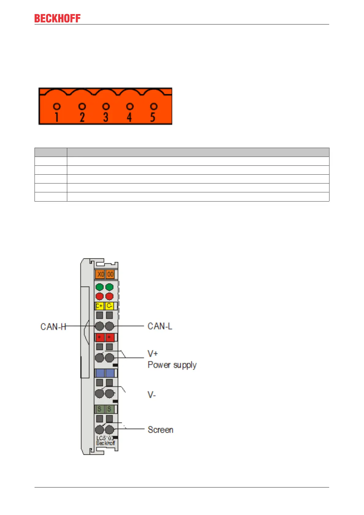
4.6 DeviceNet connection – pin assignment
A 5-pin connector is supplied for the connection of the DeviceNet bus cable. When it is plugged into the Bus
Coupler, pin 1 is at the top. The figure shows the socket in the Bus Coupler. The power supplied by this plug
is isolated from the power supply of the terminal to the right of the Bus Coupler. Both power sources must be
connected before the system can operate.
Fig.13: DeviceNet connection – pin assignment
Pin Signal
1 V+
2 CAN-H
3 GND
4 CAN-L
5 V-
LC5200 DeviceNet connection
In the low-cost LC5200 coupler, the CAN line is connected directly to the terminal points 1 (CAN-H, marked
with C+) and 5 (CAN-L, marked with C-). V+ is applied to the terminal points 2 or 6. V- is applied to the
terminal points 3 or 7. The shield can optionally be applied to terminal points 4 or 8, which are connected to
the DIN rail via an R-C circuit.
Fig.14: LC5200 - Connection diagram