Table of contents
BK52x0 and LC5200 3Version: 2.0.0
Table of contents
1 Foreword ....................................................................................................................................................5
1.1 Notes on the documentation..............................................................................................................5
1.2 Safety instructions .............................................................................................................................6
1.3 Documentation issue status ..............................................................................................................7
2 Product overview.......................................................................................................................................8
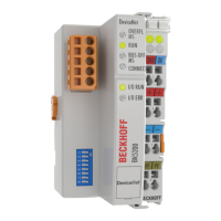
2.1 BK5200 - Introduction........................................................................................................................8
2.2 BK5250 - Introduction........................................................................................................................9
2.3 LC5200 - Introduction ......................................................................................................................10
2.4 Technical data .................................................................................................................................11
3 Basic Function Principles.......................................................................................................................12
3.1 The Beckhoff Bus Terminal system.................................................................................................12
3.2 Principle of the Bus Terminal...........................................................................................................14
3.3 DeviceNet ........................................................................................................................................15
3.3.1 DeviceNet Introduction .................................................................................................... 15
3.3.2 Data exchange................................................................................................................. 16
3.3.3 Vendor ID......................................................................................................................... 18
3.3.4 DeviceNet Group ............................................................................................................. 18
4 Mounting and wiring................................................................................................................................19
4.1 Instructions for ESD protection........................................................................................................19
4.2 Dimensions......................................................................................................................................19
4.3 Installation on mounting rails ...........................................................................................................20
4.4 Power supply, potential groups .......................................................................................................22
4.5 Electrical isolation............................................................................................................................24
4.6 DeviceNet connection – pin assignment .........................................................................................25
4.7 Bus cable lengths and pin assignment ............................................................................................26
4.8 ATEX - Special conditions (standard temperature range) ...............................................................28
4.9 ATEX - Special conditions (extended temperature range) ..............................................................29
4.10 Continuative documentation for ATEX and IECEx ..........................................................................30
5 Parameterization and Commissioning ..................................................................................................31
5.1 Start-up behaviour of the Bus Coupler ............................................................................................31
5.2 Peripheral Data in the Process Image.............................................................................................31
5.3 Configuration of the Bus Coupler ....................................................................................................35
5.4 Diagnostic LEDs ..............................................................................................................................37
5.4.1 LED displays.................................................................................................................... 38
5.4.2 LED Function Matrix ........................................................................................................ 39
6 Appendix ..................................................................................................................................................41
6.1 Composition of a process image in the Bus Coupler.......................................................................41
6.2 Support and Service ........................................................................................................................44