EasyManua.ls Logo

Beckhoff BK5200 User Manual

Beckhoff BK5200
47 pages
To Next Page IconTo Next Page
To Previous Page IconTo Previous Page
Page #17 background image
Basic Function Principles
BK52x0 and LC5200 17Version: 2.0.0
Analog outputs receive 16bits of data, i.e. two bytes, per channel. An analog output terminal with 2channels
must therefore receive 4bytes. A digital output terminal with 2channels requires a total of 2bits of data, 1bit
for each channel.
First the data from all the analog outputs
The first 4bytes of an object transmitted to the terminal strip are assigned to the first analog output terminal,
which is the analog output terminal closest to the Bus Coupler. Other terminals which are located between
the Bus Coupler and the first analog output terminals are disregarded. The next four bytes of the object go to
the second analog output terminal in the terminal strip. Any other terminals between the first and second
analog output terminals are disregarded.
Then the data for the digital outputs is transmitted in bytes
When the last analog output terminal in the terminal strip has received its data, the digital outputs are served.
Data is always transmitted byte-by-byte. The next byte from the data string contains the data for 8 digital
outputs. Bit0 and bit1 are assigned to channels 1 and 2 of the first digital output terminal after the Bus
Coupler. Other types of terminals which are located in between are ignored.
Bit2 and bit3 go to the 2 channels of the second digital output terminal, bit4 and bit5 to the third and bit6
and bit7 to the fourth. There may be other terminals located between these digital output terminals, and if so
they will be disregarded.
Additional bytes are read from the data string until the last digital output in the terminal strip has been dealt
with. If the total number of digital outputs is not a multiple of 8, there will be a number of bits left over in the
last data byte; these will be discarded.
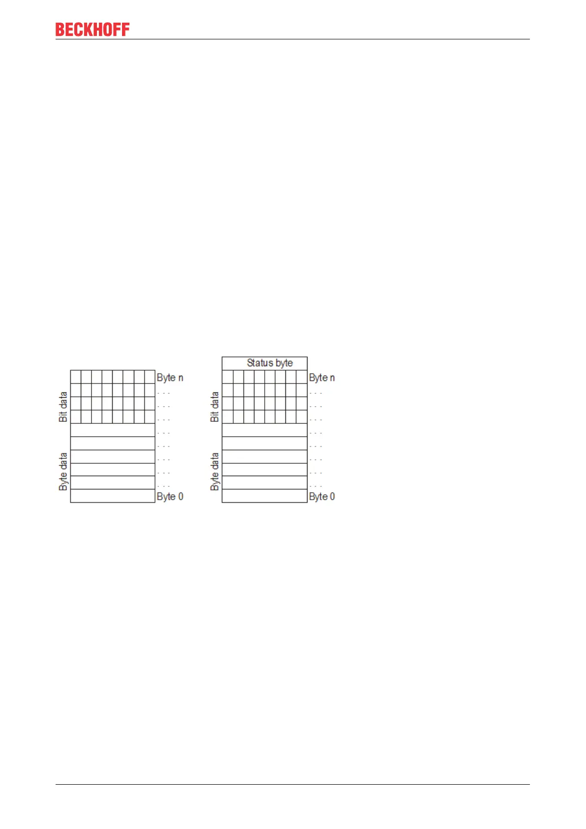
Fig.7: Data exchange
Object from the Bus Coupler to the DeviceNet master for transferring the input data
The object sent by the Bus Coupler to the DeviceNet master also contains the byte-oriented data at the
beginning, followed by the bit-oriented data. Transfers in this direction also include a status byte, which
comes right at the end of the object.
The byte-oriented data contains the values from the analog inputs and the bit-oriented data the values from
the digital inputs.
Byte-by-byte data
The first four bytes contain the data of the first analog input terminal in the terminal strip. 2bytes form the 16-
bit value of each input. The next fourbytes correspond to the next analog input terminal and so on,
analogously to the procedure described above.
Bit-by-bit data
After the byte-oriented data from all the analog inputs come the values from the digital inputs. Eightdigital
inputs are transferred in each byte. As before, if the total number of digital inputs in the terminal strip is not a
multiple of 8, the last data byte will contain one or more unused bits.

Table of Contents

Other manuals for Beckhoff BK5200

Question and Answer IconNeed help?

Do you have a question about the Beckhoff BK5200 and is the answer not in the manual?

Beckhoff BK5200 Specifications

General IconGeneral
Product TypeBus Coupler
Bus SystemEtherCAT
Input Voltage24 V DC (-15%/+20%)
Current Consumption from E-bus100 mA
Relative Humidity95 %, no condensation
Protection ClassIP20
Isolation500 V (E-bus/supply voltage)
Operating Temperature0°C to +55°C
Storage Temperature-25°C to +85°C
EMC Immunity/EmissionConforms to EN 61000-6-2/EN 61000-6-4
Data Transfer Rate100 Mbps

Summary

Foreword

Notes on the documentation

Intended audience, disclaimer, trademarks, patent pending, and copyright information.

Safety instructions

Provides detailed safety instructions, warnings, and symbol explanations for users.

Documentation issue status

Lists modifications and updates for the current version of the documentation.

Product overview

BK5200 - Introduction

Introduction to the BK5200 Bus Coupler for DeviceNet, its function and connection.

BK5250 - Introduction

Introduction to the BK5250 Compact Bus Coupler for DeviceNet, features and capabilities.

LC5200 - Introduction

Introduction to the LC5200 Low-cost Bus Coupler for DeviceNet, its design and suitability.

Technical data

Detailed technical specifications for BK5200, BK5210, BK5250, and LC5200 Bus Couplers.

Basic Function Principles

The Beckhoff Bus Terminal system

Explains the architecture of the Beckhoff Bus Terminal system, its modularity, and mounting.

Principle of the Bus Terminal

Illustrates the principle of the Bus Terminal system with its components and connections.

DeviceNet

Introduction to DeviceNet, data exchange, vendor ID, and device groups.

Mounting and wiring

Instructions for ESD protection

Provides instructions for protecting devices from electrostatic discharge during handling.

Dimensions

Details the physical dimensions and modularity of Beckhoff Bus Terminals.

Installation on mounting rails

Guides on mounting Bus Couplers and Terminals on 35 mm mounting rails and disassembly.

Power supply, potential groups

Details power supply requirements and potential groups for Bus Couplers and terminals.

Electrical isolation

Explains electrical isolation features of BK5200/BK5210 and the lack thereof in LC5200.

DeviceNet connection – pin assignment

Details the pin assignment for the 5-pin DeviceNet connector and LC5200 connection.

Bus cable lengths and pin assignment

Specifies DeviceNet baud rates, bus cable lengths, and cable layout.

ATEX - Special conditions (standard temperature range)

Outlines special ATEX conditions for use in potentially explosive areas at standard temperatures.

ATEX - Special conditions (extended temperature range)

Outlines special ATEX conditions for use in potentially explosive areas at extended temperatures.

Continuative documentation for ATEX and IECEx

Refers to additional documentation for explosion protection according to ATEX and IECEx.

Parameterization and Commissioning

Start-up behaviour of the Bus Coupler

Describes the self-test and start-up process of the Bus Coupler.

Peripheral Data in the Process Image

Explains how peripheral data is mapped into the process image for inputs and outputs.

Configuration of the Bus Coupler

Details how to set DIP switches for baud rate and MAC ID configuration.

Diagnostic LEDs

Explains LED functions, displays, and the function matrix for diagnostics.

Appendix

Composition of a process image in the Bus Coupler

Provides an example of input/output channel assignment to the process image.

Support and Service

Information on Beckhoff support, branch offices, service centers, and contact details.

Related product manuals