Parameterization and Commissioning
BK52x0 and LC5200 37Version: 2.0.0
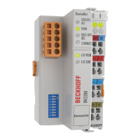
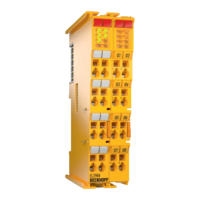
5.4 Diagnostic LEDs
After switching on, the Bus Coupler immediately checks the connected configuration. Error-free start-up is
indicated when the red "I/O ERR" LED goes out. If the "I/O ERR" LED blinks, an error in the area of the
terminals is indicated. The error code can be determined from the frequency and number of blinks. This
permits rapid rectification of the error.
The Bus Coupler has two groups of LEDs for the display of status. The upper group with four LEDs indicates
the status of the respective fieldbus. The significance of the "fieldbus status" LED is explained in the relevant
sections of this manual - it conforms to conventional fieldbus displays.
On the upper right side of the Bus Couplers are two more green LEDs that indicate the supply voltage. The
left LED indicates the presence of the 24V supply for the Bus Coupler. The right LED indicates the presence
of the supply to the power contacts.
Local errors
Two LEDs – the "I/O - LEDs" – below the above-mentioned Fieldbus Status LEDs display the operating
states of the Bus Terminals and the connection to these Bus Terminals. The green LED lights up in order to
indicate fault-free operation. The red LED blinks with two different frequencies in order to indicate an error.
The error is encoded in the blink code in the following way:
Fast flashing Start of the error code
First slow sequence Error code
Second slow sequence Error code argument
Error code Error code argument Description
1 pulse 0
1
2
EEPROM checksum error
Inline code buffer overflow
Unknown data type
2 pulses 0
n (n>0)
Programmed configuration
Incorrect table entry / Bus Coupler
Incorrect table comparison (terminaln)
3 pulses 0 Terminal bus command error
4 pulses 0
n
Terminal bus data error
Break behind terminal n (0 coupler)
5 pulses n Terminal bus error in register communication with terminal n
6 pulses 0
n (n>0)
Special fieldbus error
The number of pulses in the first sequence indicates the error type, while the second sequence indicates the
position of the last Bus Terminal before the fault. Passive Bus Terminals, such as a power feed terminal, are
not included in the count.
In the case of some errors, rectification does not cause the Bus Coupler to leave the blink sequence. The
operating state of the Bus Coupler remains "Stop". The Bus Coupler can only be re-started either by
switching the power supply off and on again, or by a scanner reset.
Insertion and removal of Bus Terminals is only permitted when switched off. The electronics in the Bus
Terminals and in the Bus Coupler are protected to a large measure against damage, but incorrect function
and damage cannot be ruled out if they are plugged in under power.
The occurrence of a fault in the course of operation does not immediately trigger the display of error codes
by the LEDs. The Bus Coupler must be requested to diagnose the Bus Terminals. The diagnostic request is
generated at power-up or through an access by the fieldbus to the Bus Coupler. This means that if no data is
being exchanged over DeviceNet when a Bus Terminal is removed from the system, the Bus Coupler will not
necessarily report an error.