Appendix
BK52x0 and LC5200 43Version: 2.0.0
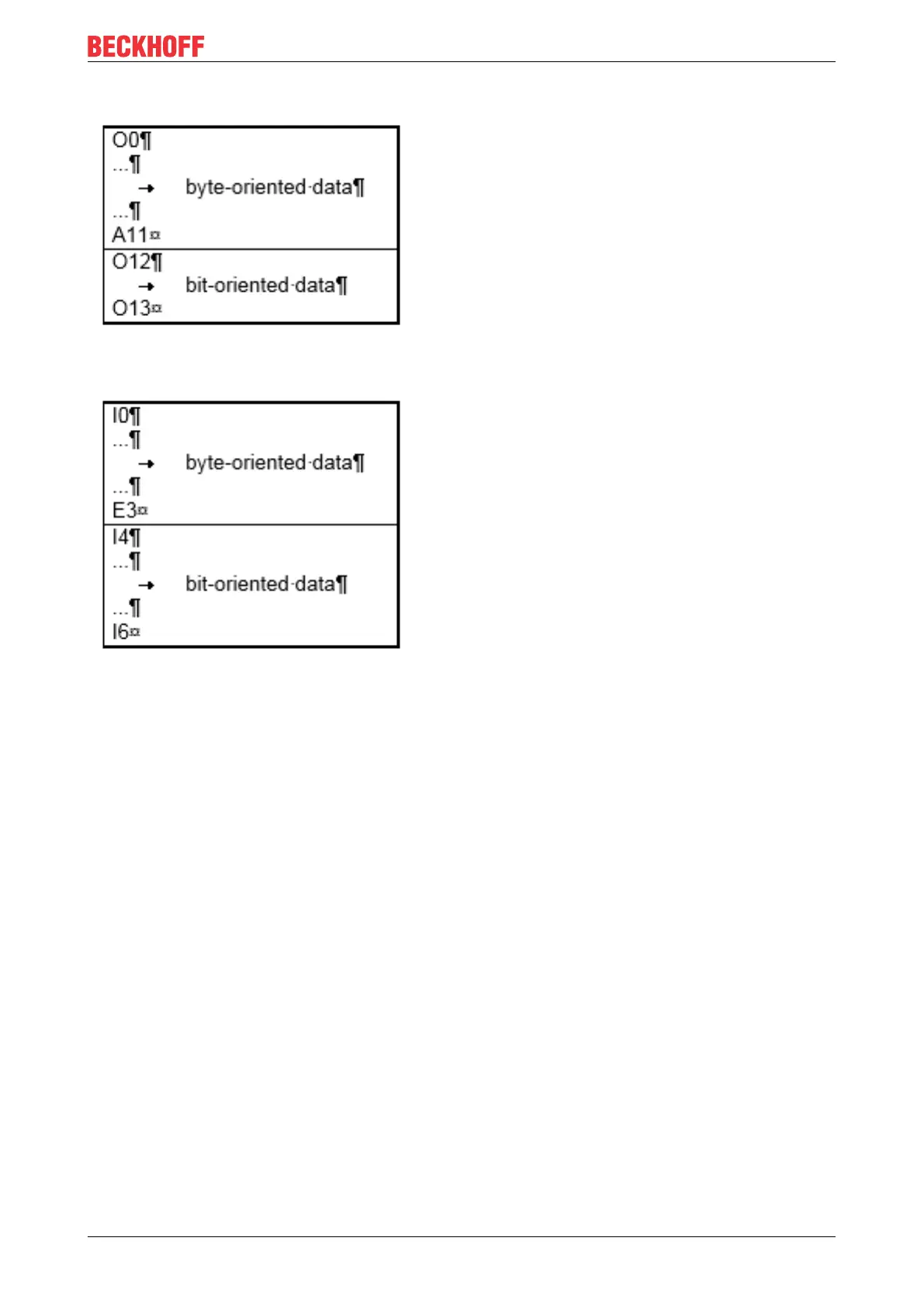
Distribution of the process image in the Bus Coupler
Fig.24: Process image in the Bus Coupler – output data
Fig.25: Process image in the Bus Coupler – input data
The base addresses I0 and O0 listed here are used as relative addresses or addresses in the Bus Coupler.
Depending on the higher-level DeviceNet system, the addresses can appear at a freely selectable position in
the process image of the controller by the bus master. You can use the configuration software of the master
to assign the bytes to the addresses in the process image of the controller.